
Piezoelectric actuator and method of producing the same

a technology of actuator and actuator body, which is applied in the manufacture/assembly of the piezoelectric/electrostrictive device, transducer type, printing, etc., can solve the problem of possible short-circuit between the bottom and top electrodes, and achieve high integration density, high nozzle density, and high resolution

Inactive Publication Date: 2008-12-04
OCE TECH
View PDF6 Cites 16 Cited by
  • Summary
  • Abstract
  • Description
  • Claims
  • Application Information

AI Technical Summary

Benefits of technology

[0007]It is an object of the present invention to provide a piezoelectric actuator which can be produced reliably and with a high yield and has an improved power gain.

Problems solved by technology

However, when, for example, sputtering or vapour deposition techniques are used within the framework of MEMS-MST technology (Micro Electro-Mechanical Systems / Micro-Systems-Technologies) for forming the top electrode and electrically contacting the same, the problem of possible short-circuits between the bottom and top electrodes has to be dealt with.

Method used


Image

  • Piezoelectric actuator and method of producing the same
  • Piezoelectric actuator and method of producing the same
  • Piezoelectric actuator and method of producing the same

Examples


Embodiment Construction

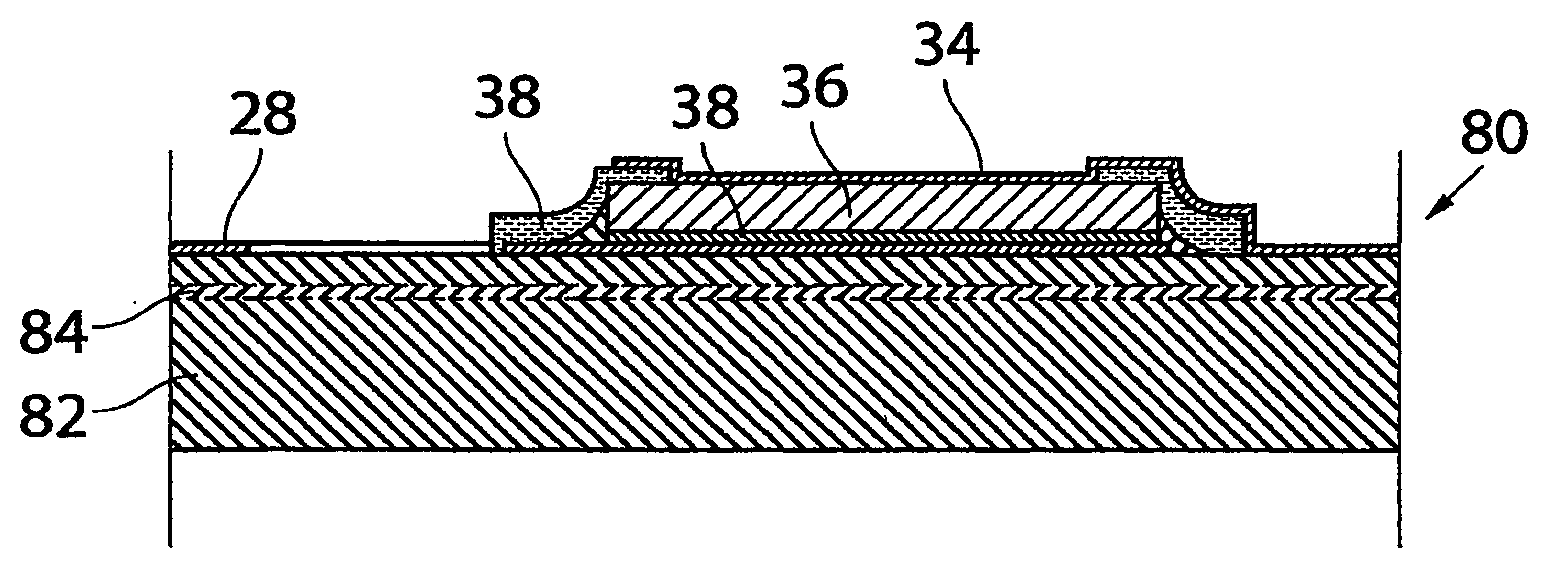
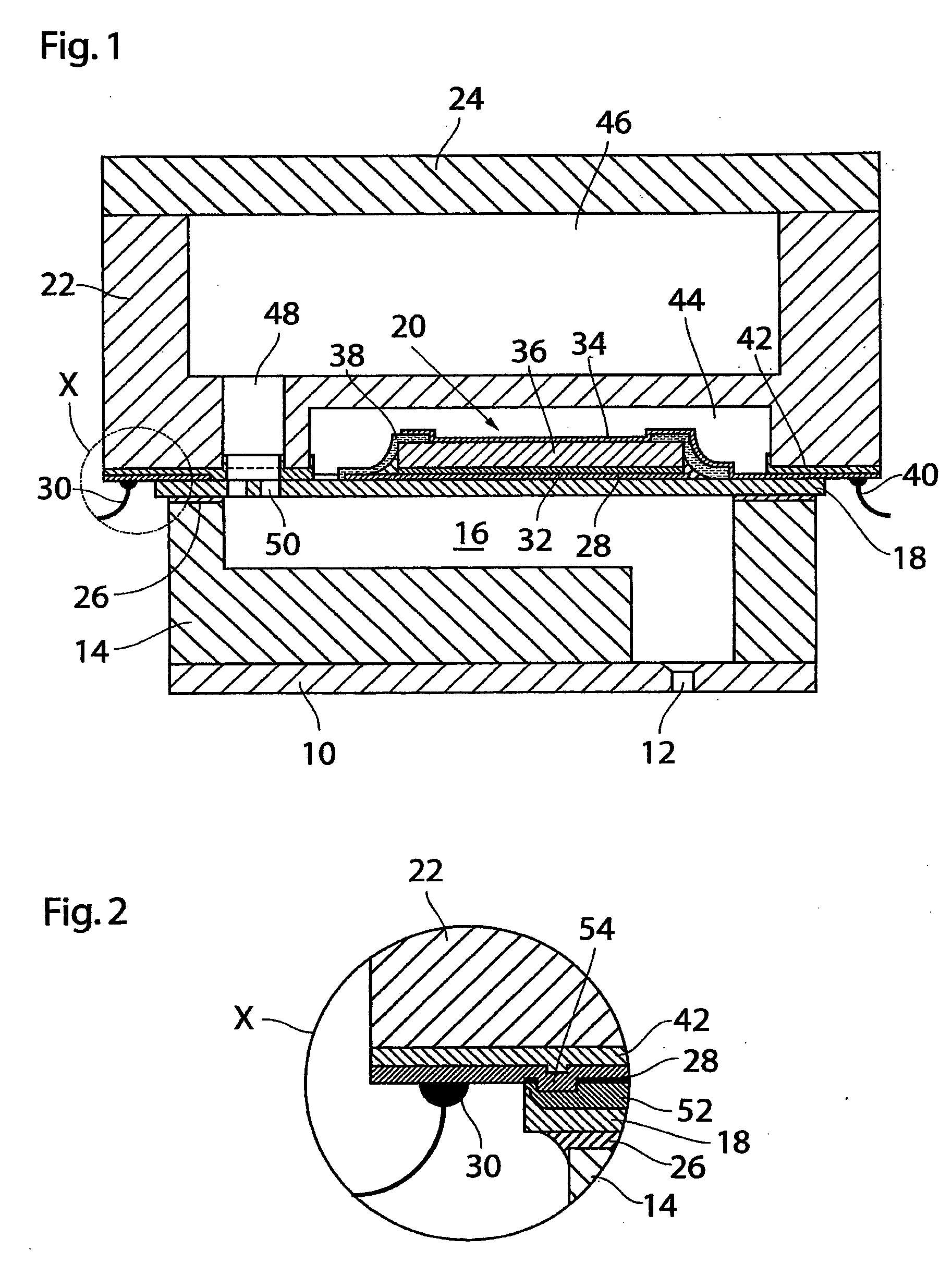
[0029]As is shown in FIG. 1, an ink jet device according to the present invention has a layered structure comprising, from the bottom to the top in FIG. 1, a nozzle plate 10 with a nozzle 12 formed therein, a chamber plate 14 defining a pressure chamber 16 that communicates with the nozzle 12, a flexible membrane 18 carrying a piezoelectric actuator 20, a distribution plate 22 for supplying liquid ink to the pressure chamber 16, and an optional cover plate 24.

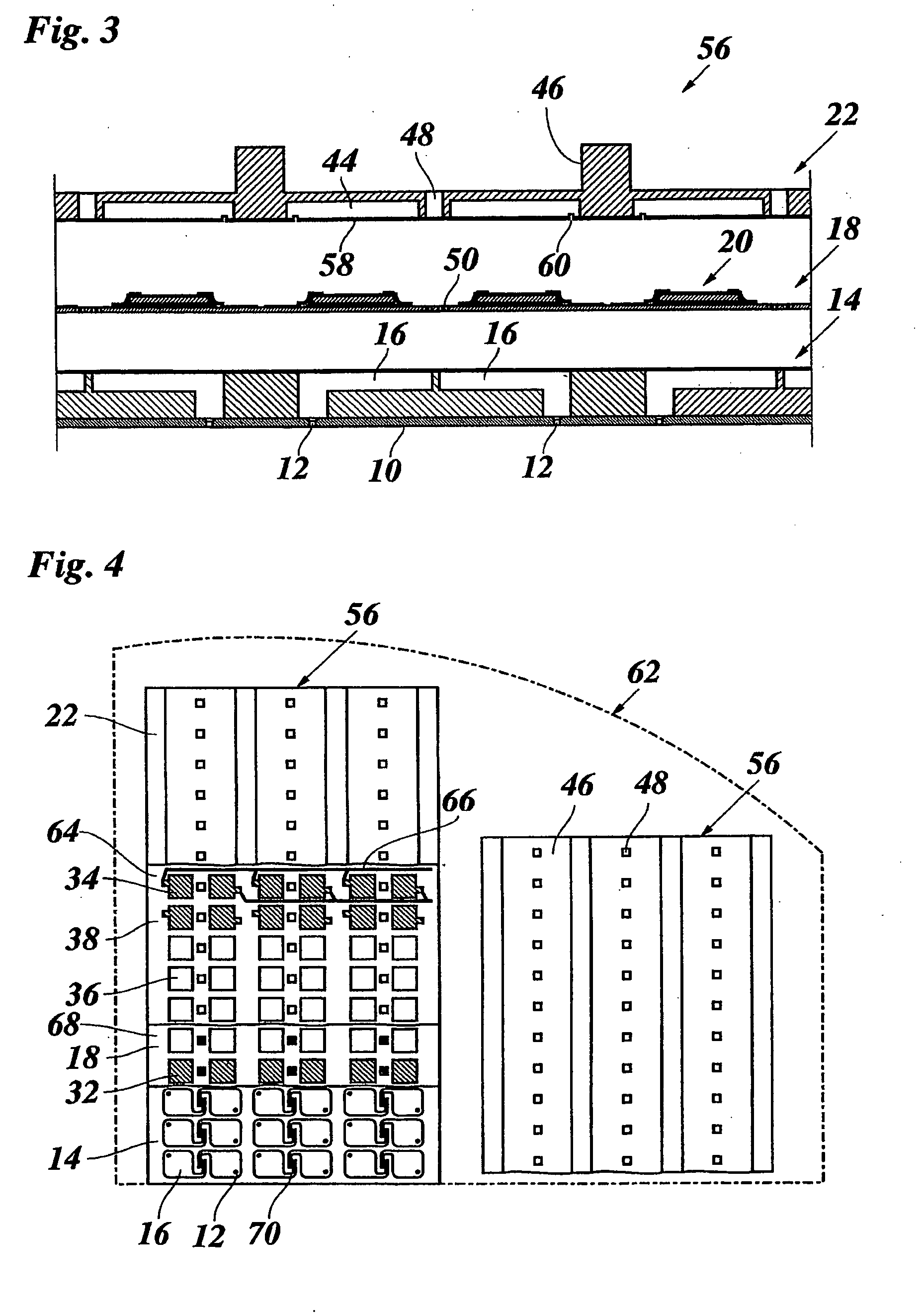
[0030]The chamber plate 14, the membrane 18 and the distribution plate 22 are preferably made of silicon, so that etching and photolithographic techniques known from the art of semiconductor processing can be utilised for reliably and efficiently forming minute structures of these components, preferably from silicon wafers. While FIG. 1 shows only a single nozzle and actuator unit, it is possible and preferable that an entire chip comprising a plurality of nozzle and actuator units, or a plurality of such chips, are formed in p...


PUM

PropertyMeasurementUnit
Thicknessaaaaaaaaaa
Piezoelectricityaaaaaaaaaa

Abstract

A piezoelectric actuator having a bottom electrode attached to a membrane, a piezoelectric layer on the bottom electrode, and a top electrode formed on the piezoelectric layer, wherein the bottom electrode extends substantially over the entire bottom surface of the piezoelectric layer, and at least a peripheral portion of a top surface of the piezoelectric layer and side faces of that layer are covered with an insulating layer, and wherein in the peripheral portion of the top surface of the piezoelectric layer the top electrode is superposed on the insulating layer.

Description

[0001]This non-provisional application claims priority under 35 U.S.C. §119(a) on European Patent Application No. 07109197.9 filed in the European Patent Office on May 30, 2007, which is herein incorporated by referenceBACKGROUND OF THE INVENTION[0002]The present invention relates to a piezoelectric actuator having a bottom electrode attached to a membrane, a thin piezoelectric layer disposed on the bottom electrode, and a top electrode formed on the piezoelectric layer, wherein the bottom electrode extends over the entire bottom surface of the piezoelectric layer, and at least a peripheral portion of a top surface of the piezoelectric layer arid side faces of that layer are covered with an insulating layer. The present invention also relates to a method of producing such an actuator.[0003]More particularly, the present invention relates to a piezoelectric actuator in an ink jet device that is used in an ink jet printer for expelling an ink droplet in response to an electrical signa...

Claims


Application Information

Patent Timeline
IPC IPC(8): H01L41/047H01L41/22
CPCB41J2/14233B41J2/161B41J2/1623B41J2/1628B41J2/1629B41J2/1631Y10T29/42B41J2/1642B41J2/1645B41J2/1646B41J2002/14241B41J2002/14258B41J2002/14491B41J2/1635
Inventor WIJNGAARDS, DAVID D.L.REINTEN, HANSSTOLK, HENDRIK J.WESTLAND, ALEX N.
Owner OCE TECH
Learn More