Airbag for Protecting a Vehicle Occupant

Active Publication Date: 2008-12-04
AUTOLIV DEV AB
View PDF18 Cites 10 Cited by
  • Summary
  • Abstract
  • Description
  • Claims
  • Application Information

AI Technical Summary

Benefits of technology

[0008]Because of the overlapping in the region of the dividing seam, the dividing seam extends through four layers of the material sections. In this way, this region of the airbag is reinforced in such a manner that it survives force applied during the inflation process without any leakage formation or crack formation occurring.
[0009]The separate material sections provide the possibility of introducing different fabric layers for the different application regions. Thus, very tear-resistant fabrics can be used for particularly stressed regions whereas light, cost-effective fabrics can be introduced for the remaining regions. In addition, particular material sections can be coated to minimize permeability and to additionally strengthen the fabric.
[0011]Pursuant to the embodiment according to claim 16, the airbag is a side airbag to protect the vehicle occupants during a side impact. To this end, the chamber regions are assigned to the pelvic region and thoracic region of the occupant and can be filled with different gas pressures. In general, the chamber assigned to the pelvic region will be filled with a higher gas pressure than the chamber assigned to the thoracic region. To this end, the airbag in the pelvic region is supposed to position itself particularly quickly and fix the center of gravity located in the pelvic region of the occupant in order to prevent the occupant from moving toward the side of the vehicle.
[0012]In order to maintain this high pressure in the airbag for the required time interval, the material sections assigned to the pelvic chamber region demonstrates a particularly heavy fabric and can additionally be coated with a silicone layer or a film, so that the material sections are characterized by high tear resistance in addition to low gas permeability.
[0013]The material sections assigned to the thoracic region are manufactured out of a more permeable fabric. Such a fabric is less expensive and has a lower weight.

Problems solved by technology

One disadvantage of this conventional arrangement of the side airbag consists of the fact that the dividing seam is subjected to high stresses because of the different pressures in the chambers, so that there exists the danger of crack formation or other leakage formation.

Method used


Image

  • Airbag for Protecting a Vehicle Occupant
  • Airbag for Protecting a Vehicle Occupant
  • Airbag for Protecting a Vehicle Occupant

Examples


Embodiment Construction

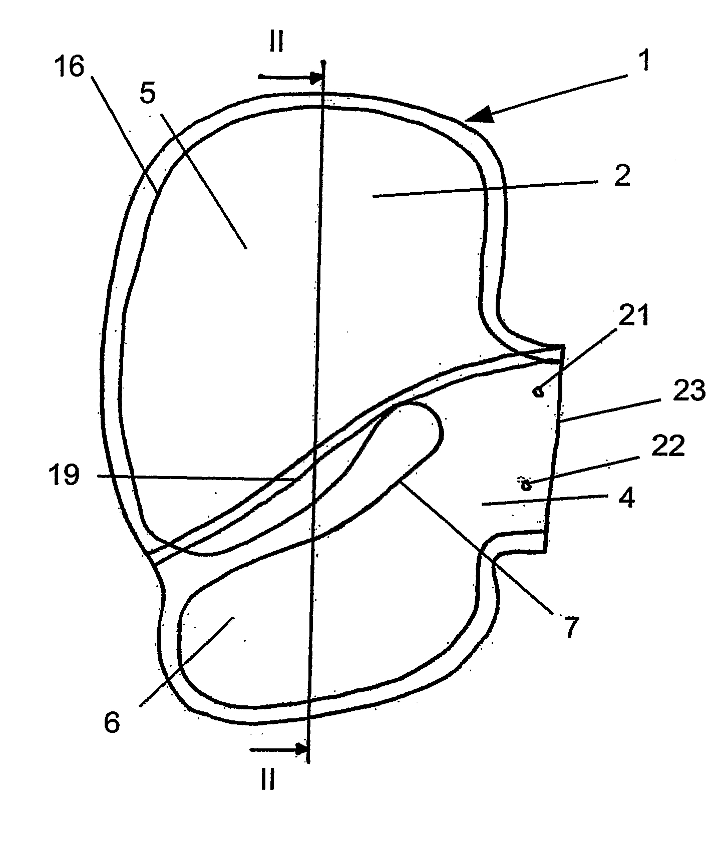
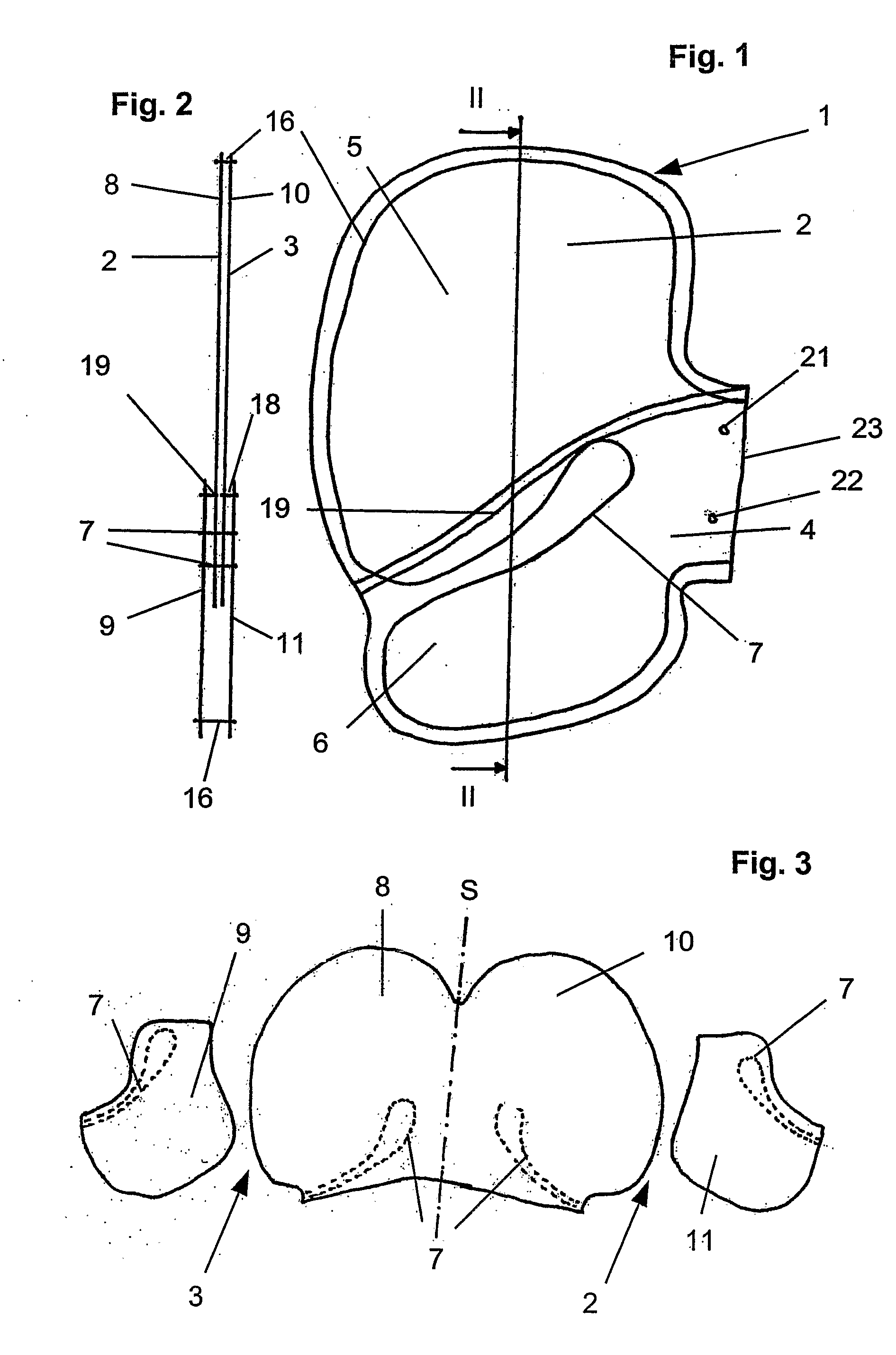
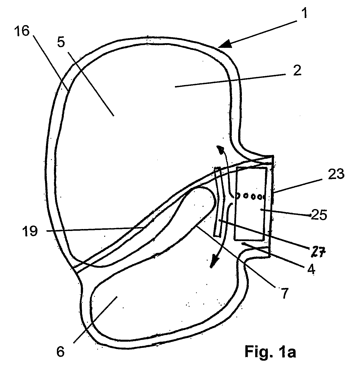
[0022]The construction of an airbag, which here is configured in the form of a side airbag, will be described in more detail on the basis of FIGS. 1 and 2. Side airbags are normally arranged in the backrest of a vehicle seat or in the region of the side door.

[0023]The airbag 1 comprises of two material layers 2, 3, which are manufactured out of fabric. These material layers 2, 3 are sewn to one another by a seam 16 along their external contour. The circumferential seam 16 leaves open the fastening region 4 of the side airbag, so that an opening 23 for connecting to a gas generator (not illustrated) is formed, Gas generators frequently demonstrate fastening bolts, which are guided through the fastening holes 21, 22 from inside when the gas generator is inserted into the airbag and thereby fasten the airbag to the housing components.

[0024]A dividing seam 7, which divides the inflatable region into two chamber regions 5, 6, is configured in an approximately central region of the airbag...


PUM


Abstract

An airbag for protecting a vehicle occupant comprising a first and a second material layer each having edge regions, wherein the first and the second layers are sewn together along the edge regions. A fastening section adapted for attaching to a part of the vehicle and connecting to a gas generator configured to inflate the airbag with a gas in response to an accident. A first and a second chamber region disposed opposite a dividing seam, wherein each of the material layers includes a first and a second material section each matched to one of the first or second chamber regions.

Description

TECHNICAL FIELD OF THE INVENTION[0001]The invention relates to an airbag to protect a vehicle occupant according to the preamble of claim 1.[0002]Conventional airbags having several chambers are usually manufactured out of two cuttings which are sewn along their edge regions and which demonstrate in darts to separate the chambers. In some airbags, the respective chambers have the task of protecting individual body areas of an occupant. Because of the different masses of the individual body areas, forces of different strength act upon them during an accident. Moreover, the weaker body areas, such as the rib cage, may not be stressed too strongly. This makes it necessary to inflate the chambers at different rates to some extent using different gas pressures.PRIOR ART[0003]U.S. Pat. No. 6,349,964 suggests a side airbag having an upper chamber assigned to projecting the thorax of the occupant and a lower chamber assigned to protect the pelvis of the occupant, the chambers being separate...

Claims


Application Information

Patent Timeline
IPC IPC(8): B60R21/233B60R21/231B60R21/232
CPCB60R21/23138B60R21/232B60R21/233B60R21/235B60R2021/23316B60R2021/23509B60R2021/23514B60R2021/23523B60R2021/23538
Inventor AHO, CHRISTIANLUCIC, DOBRILAKODMJA, STEFANSVENBRANT, EMMAKUNTZSCH, KRESTINSTOW, DAVIDBORJESON, GUSLAV
Owner AUTOLIV DEV AB
Why Eureka
Try Eureka