Wavelength tunable laser apparatus and wavelength control method

a laser apparatus and wavelength control technology, applied in the direction of electrical apparatus, laser details, semiconductor lasers, etc., can solve the problems of increasing the amount of current, the optical axis is likely to deviate, and the time needed for the control is longer, so as to achieve the effect of reducing power consumption, small size and high outpu

Active Publication Date: 2008-11-27
LUMENTUM JAPAN INC
View PDF3 Cites 13 Cited by
  • Summary
  • Abstract
  • Description
  • Claims
  • Application Information

AI Technical Summary

Benefits of technology

[0009]A wavelength control method using the phase control region brings about an advantage of manufacturing a wavelength tunable laser apparatus in a smaller size and more economically than any other method because the wavelength control method enables the apparatus to be integrated with a gain unit, and an advantage of holding an optical coupling loss small in the junction section between the gain unit and the phase control region. An amount of wavelength shift in the phase control region depends on the product of an amount of change in the index of refraction and the length of the phase control region. As a result, in a case where the amount of wavelength shift is intended to be increased, it is necessary that an amount of the current be increased whereas the index of refraction is reduced, or that the length of the phase control region be elongated.
[0012]Change in the index of refraction of the phase control region depends on an amount of current to be introduced into the phase control region. Increase in the amount of current to be introduced thereto raises an optical absorptivity. As shown in FIG. 14, an amount of optical loss is large, as 0.9 dB, and the optical output deteriorates markedly. For this reason, it is necessary that both the wavelength and the output be controlled. This brings about a problem of longer time needed for the control. In addition, the increase in the amount of the current raises power consumption so that heat from raised power consumption makes the optical axis likely to deviate. For this reason, the increase in the amount of the current is undesirable from the viewpoint of reduced reliability.
[0013]On the other hand, if the amount of wavelength shift is intended to be increased with a condition of a low carrier density with a low optical absorptivity (in other words, a low current density), the phase control region needs to be 0.4 mm in length. However, this makes the dimension of the gain chip larger for a semiconductor optical device, since the length of a gain region is approximately 1 mm in length. Enlargement of the gain chip decreases yields in terms of crystalline homogeneity, and reduces the number of devices obtained from each wafer, resulting in an increase in costs.
[0014]In this manner, the wavelength control of the conventional type is carried out by changing the amount of forward current to be introduced into the phase control region. However, this brings about the problem that the optical absorptivity increases under the condition that the carrier density is higher, and that the optical output accordingly decreases. For this reason, it is necessary that both the wavelength and the optical output are controlled. Moreover, when the optical absorptivity is intended to be smaller, the current density needs to be lower requiring a longer phase control region. With these taken into consideration, a wavelength control method has been awaited for, which enables a sufficient amount of wavelength shift to be obtained while holding the optical loss low.
[0015]The present invention aims at providing a method which enables a wavelength tunable laser apparatus using a phase control region to be manufactured in a smaller size, and to nevertheless obtain a larger amount wavelength shift while holding the optical absorptivity lower through additional use of a scheme of applying a negative bias to the phase control region. In the case of the present invention, an amount of forward current to be introduced into the phase control region and a negative bias applied thereto are used adequately for a phase control signal to be applied to the phase control region in order to shift wavelengths.
[0019]The present invention enables a wavelength tunable laser manufactured in a smaller size with lower power consumption, and operated with a higher output. Accordingly, this does not only make it possible to enhance the device performance and increase yields remarkably, but also makes it easy for the optical communication systems to be constructed more economically, to accommodate a larger capacity, and to cover a longer-distance operation.

Problems solved by technology

This brings about a problem of longer time needed for the control.
In addition, the increase in the amount of the current raises power consumption so that heat from raised power consumption makes the optical axis likely to deviate.
For this reason, the increase in the amount of the current is undesirable from the viewpoint of reduced reliability.

Method used


Image

  • Wavelength tunable laser apparatus and wavelength control method
  • Wavelength tunable laser apparatus and wavelength control method
  • Wavelength tunable laser apparatus and wavelength control method

Examples


Embodiment Construction

[0034]Descriptions will be provided hereinafter for an embodiment of the present invention.

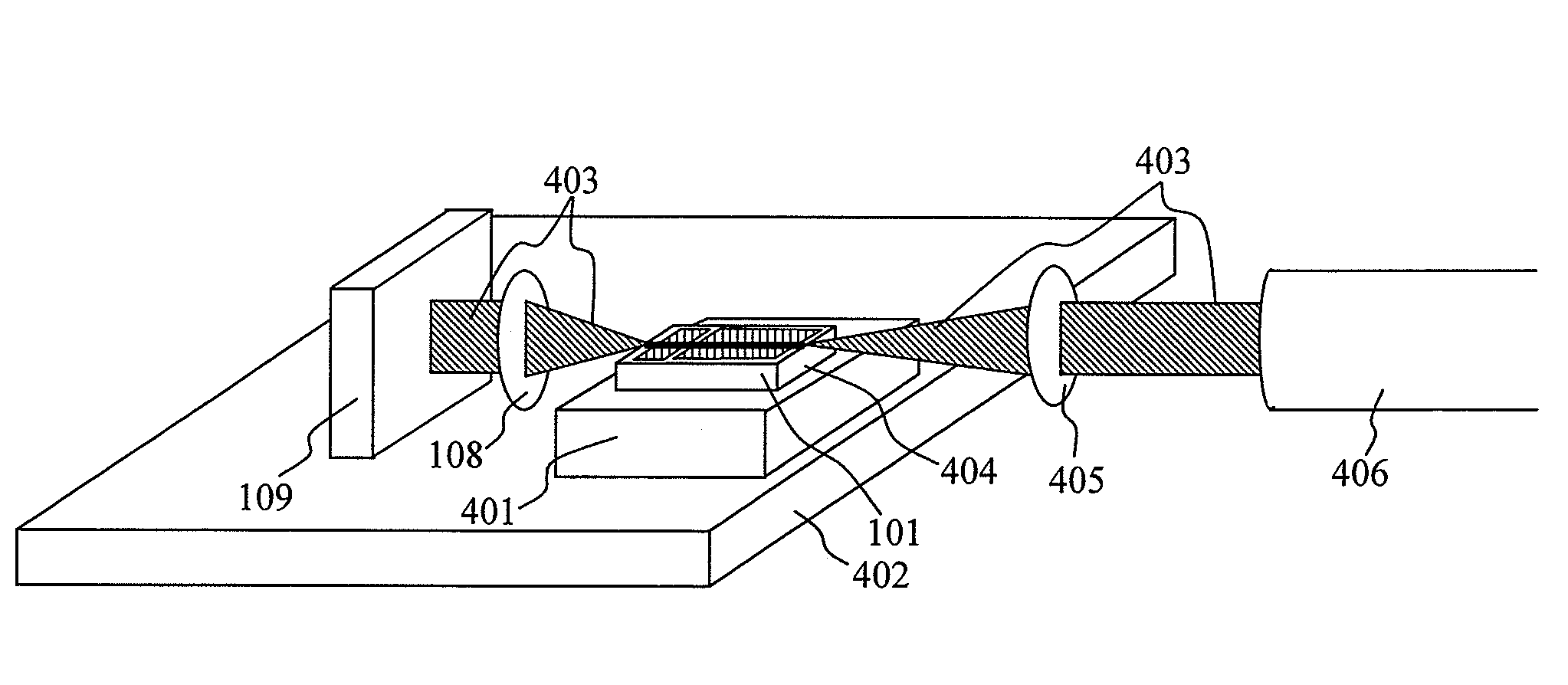
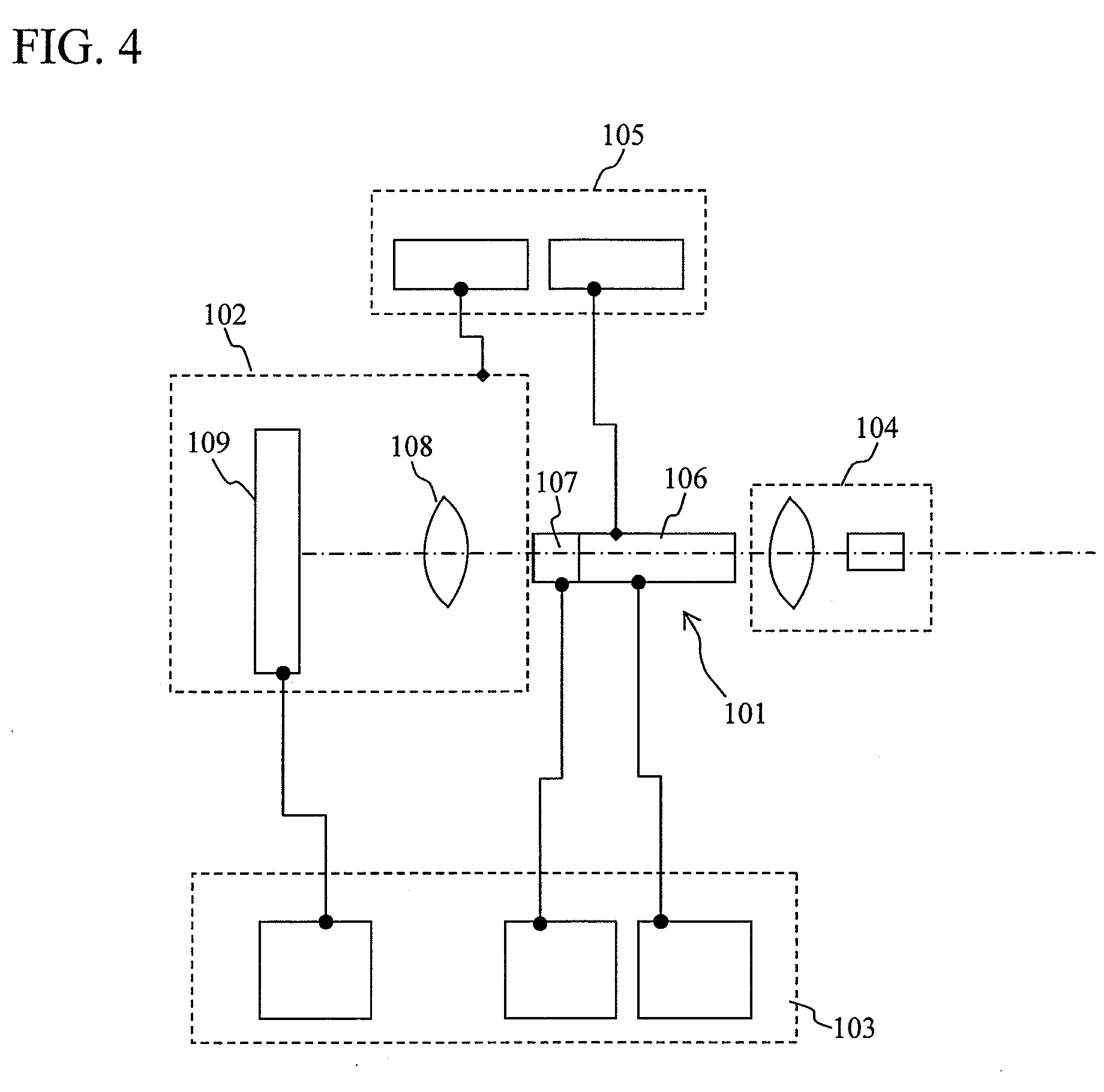
[0035]FIG. 4 is a diagram showing a rough configuration of a wavelength tunable module. FIG. 5 is a schematic diagram showing parts constituting a laser cavity. The wavelength tunable module is configured of: a light emitting device 101 which is termed as a gain chip; a wavelength controlling optical system 102; an electrical system 103; an output optical system 104 for guiding light to a fiber; a temperature controlling system 105; and the like. The gain chip 101 is an integrated device configured of a gain unit 106 for emitting light and a phase control region 107. The wavelength controlling optical system 102 is configured of: a condenser lens 108; a tunable filter 109 which is capable of selecting wavelengths, and which is also used as a mirror (although the figure shows the tunable filter also used as the mirror, a mirror may be provided separately); and the like. As shown in FIG. 5, the ...


PUM


Abstract

Included are: a gain chip having a gain unit and a phase control region; a current supply for causing a positive current to flow to the phase control region; a voltage supply for applying a bias voltage to the phase control region; and a control unit for selectively driving the current supply or the voltage supply depending on a direction of the wavelength shift. The control unit drives the current supply when a laser wavelength is to be shifted to a shorter wavelength side from a wavelength with the current supply and the voltage supply being turned off, and drives the voltage supply when the laser wavelength is to be shifted to a longer wavelength side from a wavelength with the current supply and the voltage supply being turned off.

Description

CLAIM OF PRIORITY[0001]The present application claims priority from Japanese application JP 2007-134483 filed on May 21, 2007, the content of which is hereby incorporated by reference into this application.BACKGROUND OF THE INVENTION[0002]1. Field of the Invention[0003]The present invention relates to an external-cavity wavelength tunable laser apparatus used for optical communications, and to a wavelength control method thereof.[0004]2. Descriptions of Related Art[0005]The transmission capacity of optical communications is acceleratingly increasing year after year. Wavelength division multiplex (WDM) communications have been realized as an economical, high-speed and large-capacity technique to meet the demand from the increase in the transmission capacity. WDM is a technique which simultaneously uses multiple beams (tens to one hundred wavelengths) of monochromatic light each with a wavelength not longer than a 0.01-μm interval, and which transmits mutually-different signals with t...

Claims


Application Information

Patent Timeline
IPC IPC(8): H01S3/106
CPCH01S5/06255H01S5/146
Inventor ARIMOTO, HIDEOITO, KZUHIROSASAKI, HIROYASU
Owner LUMENTUM JAPAN INC
Why Eureka
Try Eureka