Polygonal Chemiluminescent Lighting Device

a technology of chemiluminescent lighting and polygonal cylinders, which is applied in the direction of lighting and heating apparatus, refractors, and lampshades, can solve the problems of uneconomical devices, commercially unviable, and other plastic types such as vinyls, acrylics, etc., and achieve the effect of improving the light illuminating properties

Active Publication Date: 2008-11-27
CYALUME TECH
View PDF7 Cites 2 Cited by
  • Summary
  • Abstract
  • Description
  • Claims
  • Application Information

AI Technical Summary

Benefits of technology

[0008]The instant invention is a polygonal shaped vessel for containing of the “oxalate“ and “activator” component. The shaped vessel permits the distribution of light in a controlled manner so as to allow for augmented illumination of the shape of the device without increasing the amount of chemical required. The vess...

Problems solved by technology

If the vessel is actually made larger, the amount of chemical needed is increased thereby making the device uneconomical.
The corners, as disclosed, act as light concentrators to give an enhanced lighting effect but is commercially unviable.
Other types of plastics such as vinyl's, acrylics, or such are not compatible with the solvents typically ut...

Method used


Image

  • Polygonal Chemiluminescent Lighting Device
  • Polygonal Chemiluminescent Lighting Device

Examples


Embodiment Construction

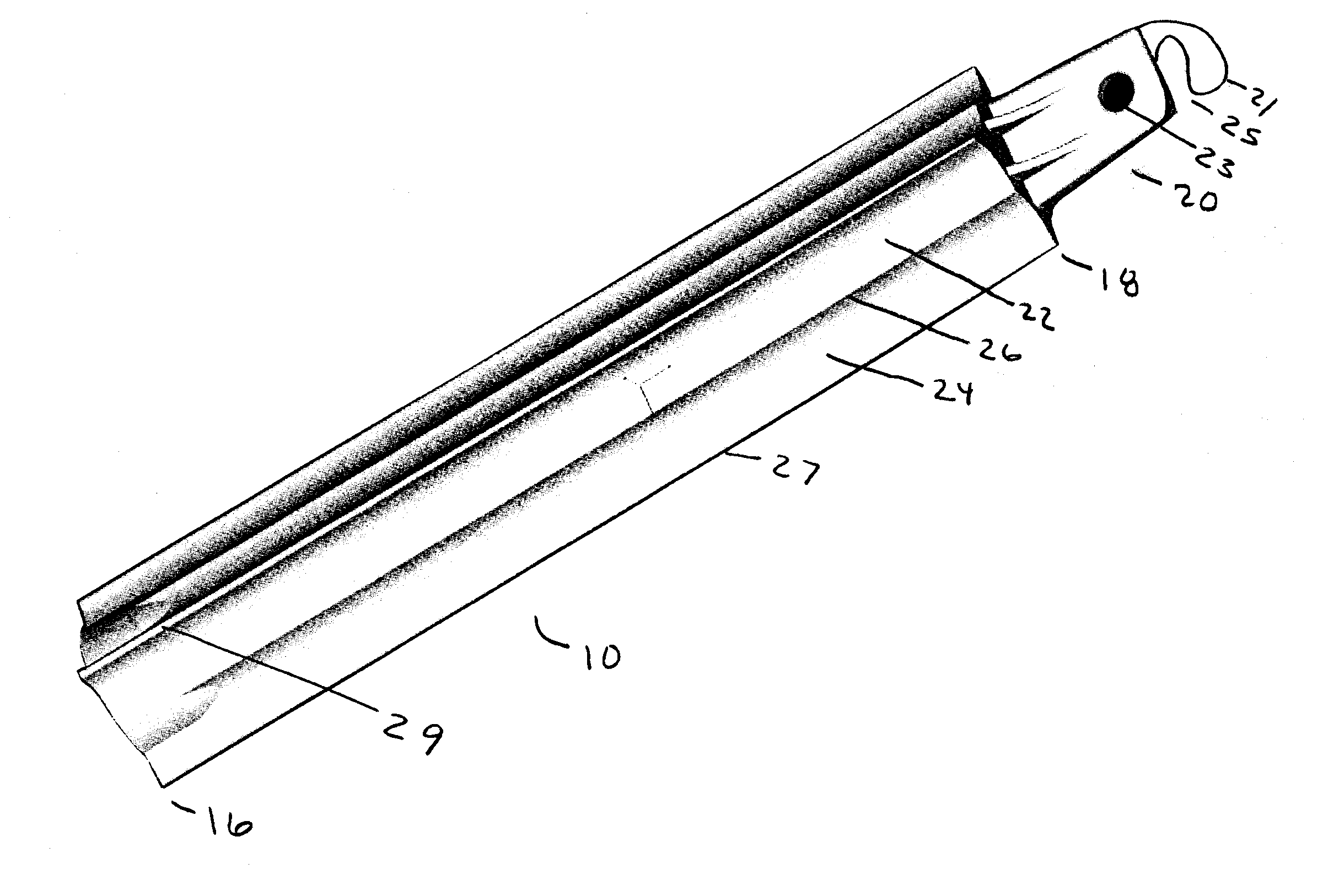
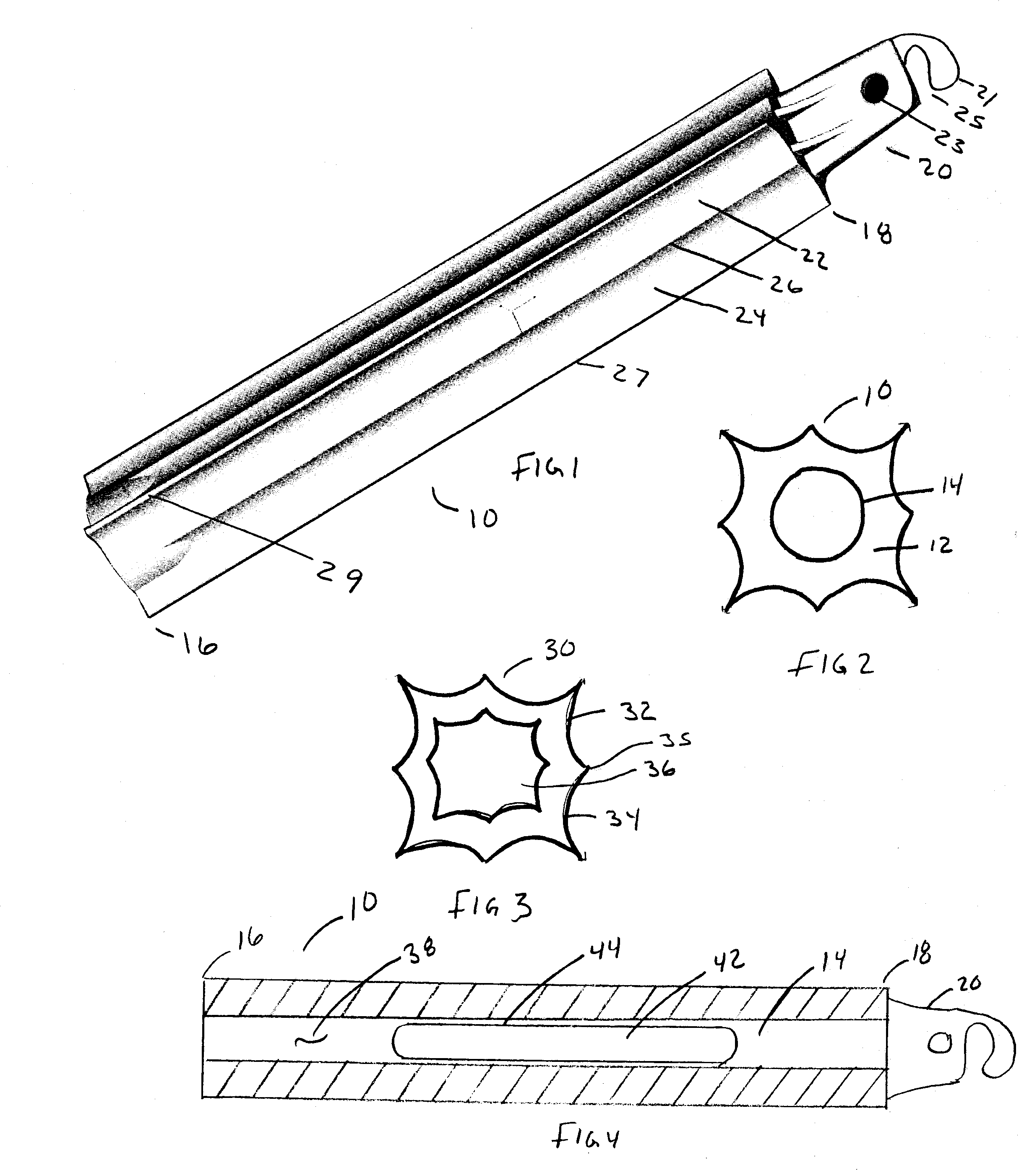
[0019]Although the invention is described in various specific embodiments, it will be readily apparent to those skilled in this art that various modifications, rearrangements and substitutions can be made without departing from the spirit of the invention. The scope of the invention is defined by the claims appended hereto. With reference to FIGS. 1 and 2, set forth is an injection molded rectangular shaped housing 10 having a square shaped cross section 14 and tubular inner annulus 14. In the preferred embodiment, the outer dimensions of the housing 10 are 1 inch by 1 inch by six inches long. The inner tubular annulus 14 has a diameter of about 0.5 inches and a length of 5.85 inches extending from one end 16 of the device and almost all the way through the device to the second end 18. A projection 20 may extend outwardly for use in coupling to a lanyard or the like. The projection includes a hook shaped member 21 defining an eye 23 and an open side 25 for admitting a horizontal sup...


PUM


Abstract

A chemiluminescent illuminated device employing a light-filtering injection molded polygonal shaped container that is scalloped to form an augmented illumination surface. The shaped housing includes a round shaped or form following chemical holding section. The lighting effects generated by the chemiluminescent chemical is enhanced by the polygonal shape and the inherent optical properties.

Description

FIELD OF THE INVENTION[0001]This invention is directed to the field of chemiluminescent lighting devices and, in particular, to the shaping of chemiluminescent vessels for purposes of enhancing illumination without increasing chemical levels.BACKGROUND OF THE INVENTION[0002]Chemiluminescent devices are non-incandescent products which produce light from a chemical mixture. The basic chemiluminescent process produces light when two chemical solutions are combined. The solutions are kept physically separated prior to activation. Physical separation typically consists of a sealed frangible glass vial containing a first solution that is placed within a second solution, both of which are housed in a sealed flexible vessel. When the vessel is flexed, the glass vial is ruptured thereby releasing the vial solution wherein the admixed chemical creates a reaction that produces light.[0003]The chemical solutions are generally referred to as the “oxalate” component and the “activator” component....

Claims


Application Information

Patent Timeline
IPC IPC(8): F21K2/06
CPCF21K2/06
Inventor CRANOR, EARL
Owner CYALUME TECH
Why Eureka
Try Eureka