Input system and input device
- Summary
- Abstract
- Description
- Claims
- Application Information
AI Technical Summary
Benefits of technology
Problems solved by technology
Method used
Image

Examples
first embodiment
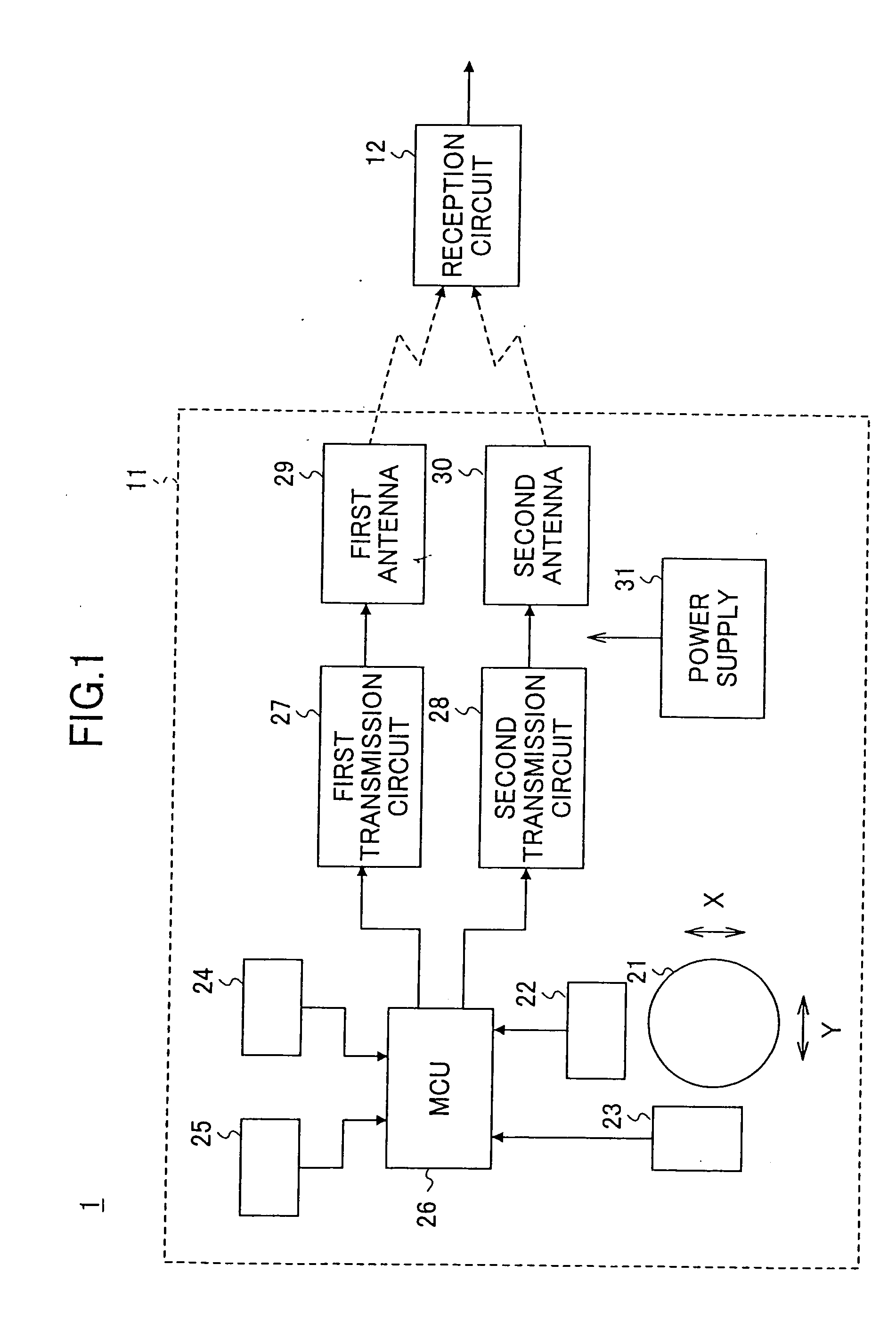
[0039]FIG. 1 is a block diagram of an input system 1 according to the present invention.
[0040]The input system 1 is applied as an input system for a computer. The input system 1 includes an input device 11 and a reception circuit 12. Information input from the input device 11 is supplied via two radio communication paths to the reception circuit 12. The reception circuit 12 supplies the information from the input device 11 to the computer.
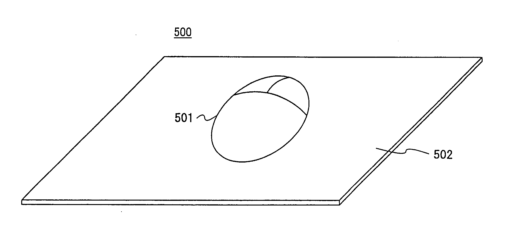
[0041]The input device 11 is a mouse and includes a coordinate detection ball 21, sensors 22 and 23, switches 24 and 25, a microprogram control unit (MCU) 26, first and second transmission circuits 27 and 28, first and second antennas 29 and 30, and a power supply 31.
[0042]Each of the sensors 22 and 23 includes a rotary encoder and generates pulses whose number corresponds to a rotational displacement amount of the coordinate detection ball 21. The detection results of each of the sensors 22 and 23 are supplied to the MCU 26. The MCU 26 computes di...
second embodiment
[0066]FIG. 7 is a block diagram of an input system 100 according to the present invention. In FIG. 7, the same elements as those of FIG. 1 are referred to by the same numerals, and a description thereof will be omitted.
[0067]The input system 100 differs from the input system 1 of FIG. 1 in a reception circuit structure. A reception circuit 110 of this embodiment includes first and second reception parts 111 and 112 for receiving the radio waves of the first and second carrier frequencies f1 and f2 transmitted from the first and second antennas 29 and 30, respectively, and a synthesis part 113 that synthesizes first and second received signals from the first and second reception parts 111 and 112, respectively.
[0068]According to this embodiment, the radio waves of the first and second carrier frequencies, f1 and f2 are individually received and then synthesized. Therefore, the radio waves are efficiently received and demodulated, so that received signal levels can be raised.
[0069]Acc...
third embodiment
[0070]FIG. 8 is a block diagram of an input system 200 according to the present invention. In FIG. 8, the same elements as those of FIG. 1 are referred to by the same numerals, and a description thereof will be omitted.
[0071]The input system 200 differs from the input system 1 of FIG. 1 in an input device structure. An input device 210 of this embodiment includes a transmission circuit 211 and a switching circuit 212 instead of the first and second transmission circuits 27 and 28 of the input device 11 of FIG. 1.
[0072]A switching control signal Sc supplied from the MCU 26 allows the transmission circuit 211 to transmit a signal alternately to the first and second antennas 29 and 30. By thus outputting the same data of the same carrier frequency alternately from the first and second antennas 29 and 30, a space diversity effect can be produced. Therefore, a signal can be efficiently transmitted irrespective of a state of the input device 210.
[0073]FIG. 9 is a block diagram of the tran...
PUM
 Abstract
Description
Claims
Application Information
 - R&D
- Intellectual Property
- Life Sciences
- Materials
- Tech Scout
- Unparalleled Data Quality
- Higher Quality Content
- 60% Fewer Hallucinations
Browse by: Latest US Patents, China's latest patents, Technical Efficacy Thesaurus, Application Domain, Technology Topic, Popular Technical Reports.
© 2025 PatSnap. All rights reserved.Legal|Privacy policy|Modern Slavery Act Transparency Statement|Sitemap|About US| Contact US: help@patsnap.com