Broadband high-gain magnetic field annular test antenna based on resonance principle and design method

A test antenna, high-gain technology, applied in the direction of antenna support/installation device, measurement power, measurement device, etc., can solve the problem of unadjustable test frequency band

Active Publication Date: 2013-09-11
XIAN KAIRONG ELECTRONICS TECH
View PDF5 Cites 0 Cited by
  • Summary
  • Abstract
  • Description
  • Claims
  • Application Information

AI Technical Summary

Problems solved by technology

In recent years, in the field of electromagnetic compatibility, the requirements for anti-electromagnetic interference performance of products have become higher and higher. Since the electromagnetic interference radiation frequency band of various electronic products is becoming wider and wider, and the low frequency band is particularly dense, and the current used in this field Most of the magnetic field antennas are narrow-band magnetic field antennas, and the test frequency band cannot be adjusted, so a broadband high-gain loop test antenna that can adjust the test frequency band is required

Method used


Image

  • Broadband high-gain magnetic field annular test antenna based on resonance principle and design method

Examples


Embodiment Construction

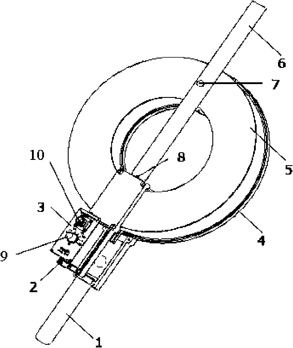
[0015] Such as figure 1 As shown in the structural diagram of the loop test antenna, it includes test handle 1, resonance control circuit 2, control panel 3, antenna radiator 4, antenna box body 5, positioning pull rod 6, positioning screw 7, limit rod 8, band switch 9, N-type radio frequency connector 10; antenna radiator 4 is built in the antenna box body 5; positioning rod 6 is fixed across the antenna box body 5 by positioning screws 7, and one end of the positioning rod 6 is limited by a limit rod 8. Distance; the limit rod 8 is connected and fixed with the test handle 1 by the control panel 3, the N-type radio frequency connector 10 and the band switch 9 are embedded on the control panel 3, and are connected to the resonance control circuit 2 inside the control panel 3 .

[0016] The antenna radiator 4 is a planar spiral coil with an inner diameter of 169 mm and an outer diameter of 349 mm, and the resonance device is composed of the antenna radiator 4 (coil) and the re...


PUM


Abstract

The invention belongs to the technical field of electronic test and measurement and particularly relates to a broadband high-gain magnetic field annular test antenna based on a resonance principle and a design method. The broadband high-gain magnetic field annular test antenna based on the resonance principle is characterized by at least comprising a test handle, a resonance control circuit, a control panel, an antenna radiator, an antenna box body, a locating pull rod, a locating screw, a limit lever, a wave band switch and an N-shaped radiofrequency connector, wherein the antenna radiator is arranged in the antenna box body, the locating pull rod bestrides the antenna box body and is fixed by the locating screw, the distance of the locating pull rod is limited by the limit lever at one end of the locating pull rod, the limit lever is connected and fixed with the test handle by the control panel, and the N-shaped radiofrequency connector and the wave band switch are embedded in the control panel. The invention is suitable for shielding efficiency test of a shielding chamber, a shielding square cabin and a cabinet and radiation interference leakage detection test of large-scale electronic equipment and systems.

Description

technical field [0001] The invention belongs to the technical field of electronic testing and measurement, in particular to a wide-band high-gain magnetic field loop test antenna and a design method based on the resonance principle. Background technique [0002] In order to meet the needs of the development of modern electronic technology, the research and development of antennas are mainly developed in the direction of small size, wide frequency band, high gain and adjustable. In recent years, in the field of electromagnetic compatibility, the requirements for the anti-electromagnetic interference performance of products have become higher and higher. Since the electromagnetic interference radiation frequency band of various electronic products is becoming wider and wider, and the low frequency band is particularly dense, and the current used in this field Most of the magnetic field antennas are narrow-band magnetic field antennas, and the test frequency band cannot be adju...

Claims


Application Information

Patent Timeline
Patent Type & Authority Patents(China)
IPC IPC(8): H01Q1/22H01Q1/36G01R31/00
Inventor 邱扬刘海宁李国正
Owner XIAN KAIRONG ELECTRONICS TECH
Why Eureka
Try Eureka