
Method for Allocating Radio Resource in Multi-Carrier Time Division Duplex Mobile Communication System

Active Publication Date: 2008-11-20
DATANG MOBILE COMM EQUIP CO LTD
View PDF2 Cites 24 Cited by
  • Summary
  • Abstract
  • Description
  • Claims
  • Application Information

AI Technical Summary

Benefits of technology

[0021]It should be noted that taking the design complexity of the terminal into account, uplink pilot signals currently are allowed to be transmitted only on the main carrier for UpPCHs. However, with the development of the terminal technology, it may be possible to transmit uplink pilot signals on the auxiliary carriers and thus interference may be mitigated.
[0022]Compared with the radio resource allocation method in the single carrier TD-SCDMA system according to the current standard, the method of the present invention can greatly improve the system efficiency and capacity by arranging common control channels only on the main carrier and traffic channels on the auxiliary carriers. The present invention can make the management and control simple by regarding a cell or a sector served by a base station with multi-carriers and covering a same or approximately a same area as one cell (the number of the cells is reduced), and the increase of resources in the local cell can contribute to the implementation of the DCA function. By transmitting downlink pilot signals only on the main carrier (i.e. the terminal only receives different downlink pilot codes from neighboring cells on the main carrier), which makes the number of the different downlink pilot codes possibly received from neighboring cells reduced, the present invention can contribute to the cell search of the terminal, contribute to the random access and handover and avoid many wrong handovers, so that the random access of the terminal is easier and no extra cost and complexity is required. The present invention can improve and perfect the multi-carrier TDD mobile communication system since neighboring base stations use different frequencies of the main carriers and reduce the inner system interference (downlink pilot timeslot signals from neighboring co-frequency base stations interfere uplink access timeslot signals of the local cell).

Problems solved by technology

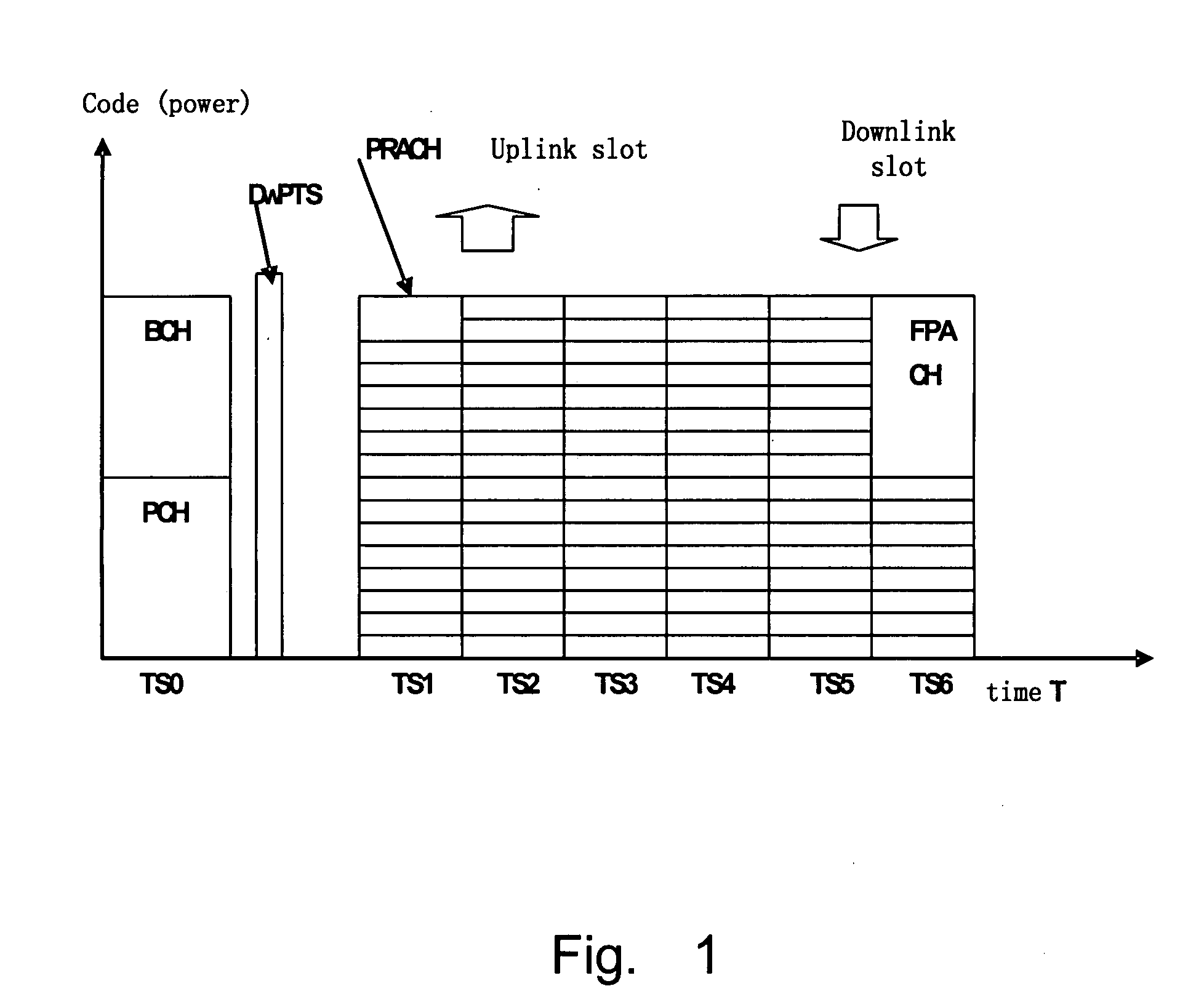
(1) Low system efficiency. Since each carrier must be configured with common channels, each carrier's channel resource for uplink and downlink traffic is reduced greatly. For example, TS0 of each carrier has been allocated to BCH and PCH; in a downlink timeslot, such as TS6, 8 code channels must be allocated to FPACH; in a uplink timeslot, such as TS1, 2 code channels must be allocated to PRACH. Thus when spreading factor is 16, only 86 (14+8+4×16) code channels can be allocated to uplink and downlink traffic by each carrier, in another word, only 21 bidirectional voice service or a unidirectional 384 kbps data service can be supported.
(2) Complicated management and control leading to efficiency decrease of some functions. The system considers that the same base station in the same geographical position covers three cells, which makes the number of cells increases, and increases the management and control complexity. For an important function of dynamic channel allocation (DCA) in the mobile communication system, since the execution of this function can only occupy the resources of the local cell while the resources of the local cell is very limited (spreading factor is 16 and available timeslots and code channels are limited, i.e., available overall resources which can be allocated are limited), the DCA technology can not put to effect because of the limited resources.
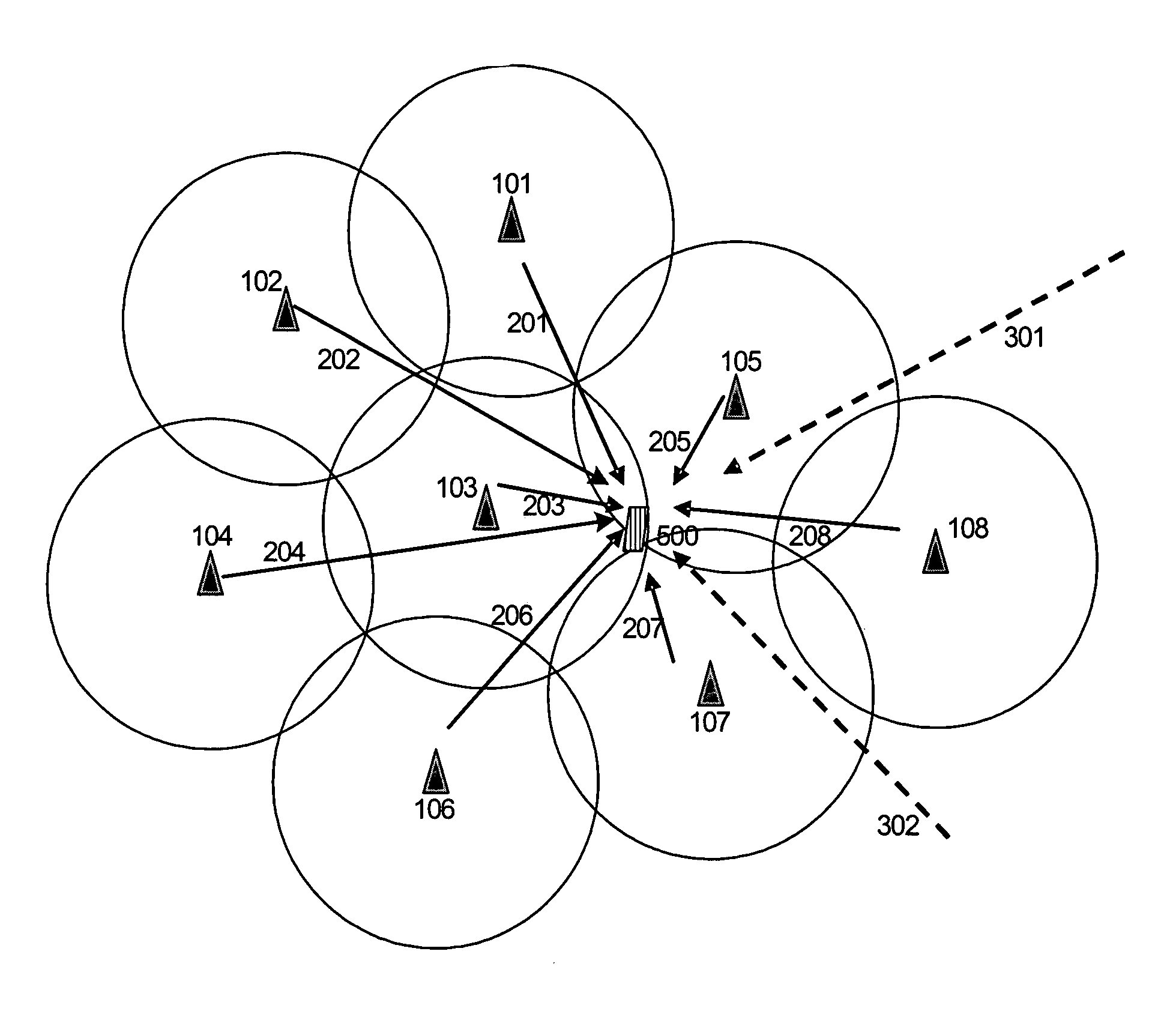
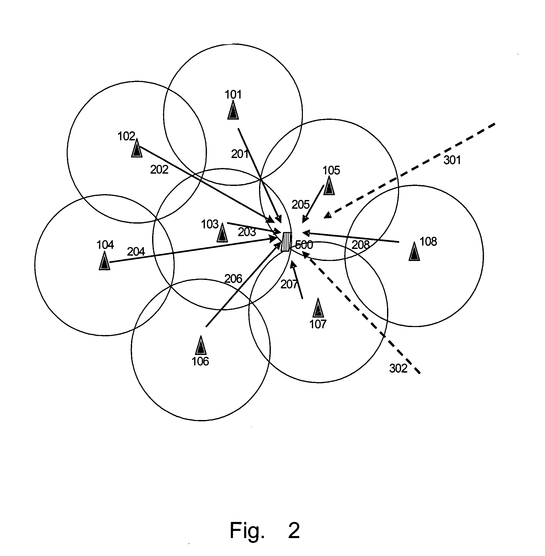
(3) It will be hard for the system to process a random access or a handover of a terminal, which causes detection difficulty. In the cellular mobile communication system, the terminal may move to a position near 3 to 6 base stations. FIG. 2 shows a typical cellular mobile network which illustrates base stations 101, 102 . . . 108 (represented by triangles respectively) and the position of terminal 500 (represented by a diamond), wherein the nearest base stations are 103, 105 and 107 and the near base stations are 101, 102, 103, 104, 106, 108 and the terminal 500 receives signals 201, 202. . . . 208 from the base stations 101, 102 . . . 108 respectively and interference signals 301 and 302 from distant co-frequency base stations. The terminal 500 may receive different downlink pilot codes from neighboring cells on a downlink pilot timeslot (DwPTS) of each carrier, wherein the number of the downlink pilot codes equals to a product of the number of the base stations and the number of carriers of each base station. For example, if an occupied bandwidth is 10 MHz and each base station may use 6 carriers, the terminal 500 may receive signals from around or more than 20 cells. At this time, since it is impossible for the downlink pilot signals from different cells to be synchronous, SNR can reach −5 to −8 dB on each carrier frequency, which makes it more difficult for the terminal to search for and to access the cell; while in a connected mode (communication mode), if each base station uses multi-carriers, the terminal may detect signals from around 10 different cells and levels of these signals are close, which causes detection difficulty. The above cases thus lead to many wrong handovers and handover difficulty, which causes the system unstable.
(4) In the cellular network, after being transmitted for a far distance, the downlink pilot signals (transmitted in DwPTS), such as 301 and 302 shown in FIG. 2, of distant co-carrier frequency base stations may interfere uplink pilot signals transmitted by the terminal 500, which increases the difficulty of accessing the system.

Method used


Image

  • Method for Allocating Radio Resource in Multi-Carrier Time Division Duplex Mobile Communication System
  • Method for Allocating Radio Resource in Multi-Carrier Time Division Duplex Mobile Communication System
  • Method for Allocating Radio Resource in Multi-Carrier Time Division Duplex Mobile Communication System

Examples


Embodiment Construction

[0028]The present invention discloses a channel arrangement (resource allocation) method for a multi-carrier base station and is illustrated by taking a TD-SCDMA system as an example. In the invention, a cell or a sector served by a base station with multi-carriers and covering a same or approximately a same area is regarded as one cell.

[0029]FIG. 3 shows the architecture of a multi-carrier multi-cell base station. This multi-carrier base station can support one or more cell (or sector) and includes a common control and interface unit 530, a multi-carrier base band processing unit 520, multi-carrier IF processing units 511, 512, 513 . . . 51n and multi-carrier RF units 501, 502, 503 . . . 50n. The RF units 501, 502, 503 . . . 50n include antennas (single antenna or an antenna array composed by multiple antennas), feed lines and RF transceivers. Base station design including working frequency bandwidth and output power level is determined according to the supported number of carriers...


PUM


Abstract

A method for distributing wireless resource in multicarrier time division duplexing mobile communication system, such as TD-CDMA system, to overcome the shortage of 3GPP single carrier cell channel distribution technology of covering more lager area in composing cellular system, which contains using an area of covering same or almost same as a cell, selecting one carrier as main carrier and other carriers as auxiliary carrier, the frequency of main carrier is as different as possible, setting all public control channel in main carrier, the left resource of main carrier and resource of auxiliary carrier are used in uplink and downlink service channel, the arrangement of public channel in main carrier is same with that in single carrier cell.

Description

FIELD OF THE INVENTION[0001]The present invention relates to mobile communication technologies, more particularly to a radio resource (channel) allocating method for a multi-carrier time division duplex (TDD) mobile communication system realizing multi-carrier working mode in a cell or a sector such as a multi-carrier cell in a time division synchronous code division multiple access (TD-SCDMA) system.BACKGROUND OF THE INVENTION[0002]Only single carrier working mode is specified in a current 3rd generation TDD communication mode specification (refer to relating technology specifications in 3GPP). FIG. 1 shows a single carrier cell channel allocation in a TD-SCDMA system specified in 3GPP standard. As shown in FIG. 1, taking a TD-SCDMA system with 3 carriers (f0, f1, f2) as an example, an independent cell may be constituted by one carrier. In each carrier, a broadcasting channel (BCH) and a paging channel (PCH) are arranged in its TS0 timeslot, an uplink physical random access channel...

Claims


Application Information

Patent Timeline
IPC IPC(8): H04Q7/20H04W16/00
CPCH04L5/0016H04L5/0053H04W16/02H04W28/04H04W72/00H04W72/02H04W72/04H04W72/0453H04W72/082H04W72/541H04L5/22H04W16/24
Inventor LI, FENGLI, SHIHEHE, YUSONGYANG, GUILIANG
Owner DATANG MOBILE COMM EQUIP CO LTD
Learn More