
Apparatus, System and Method for Calibrating and Verifying a Wireless Communication Device

a wireless communication and device calibration technology, applied in the field of production testing of wireless communication systems, can solve the problems of not being able to direct, e.g., wired, and generally available digital control connection between the device under test (dut) and the test controller, and achieve the effect of reducing the difficulty of production testing, avoiding the possibility of failure, and avoiding failur

Active Publication Date: 2008-11-20
LITEPOINT
View PDF69 Cites 44 Cited by
  • Summary
  • Abstract
  • Description
  • Claims
  • Application Information

AI Technical Summary

Benefits of technology

[0009]In one example, an apparatus for testing a wireless communication device includes a receiver, a capture module, and a control module. The receiver receives at least one test packet transmitted from the wireless communication device. The capture module captures at least a portion of the at least one test

Problems solved by technology

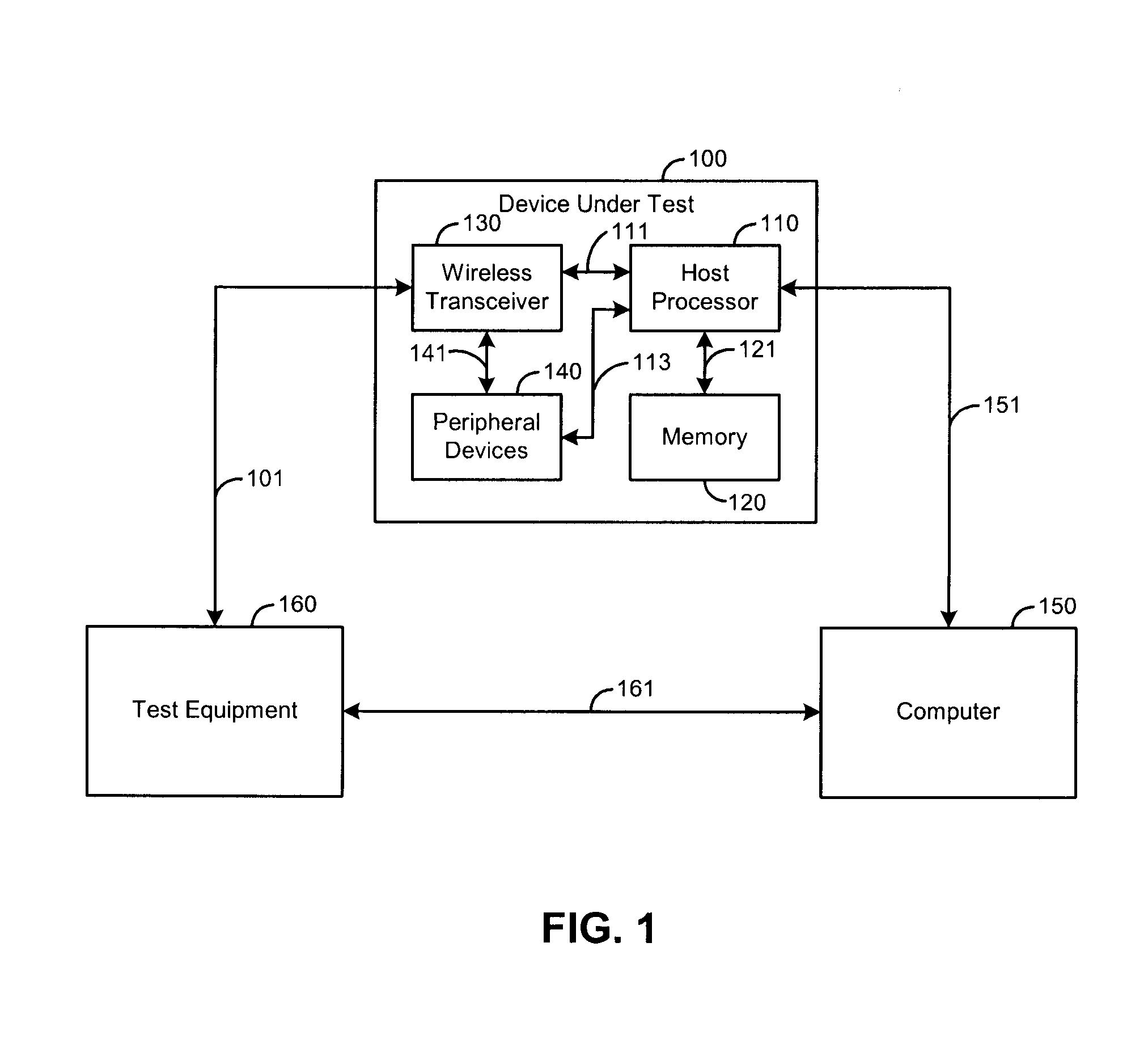
As is well known, a problem with production testing of such embedded transceivers is that no direct, e.g., wired, digital control connection is generally available between the device under test (DUT) and the test controller (e.g., personal computer).
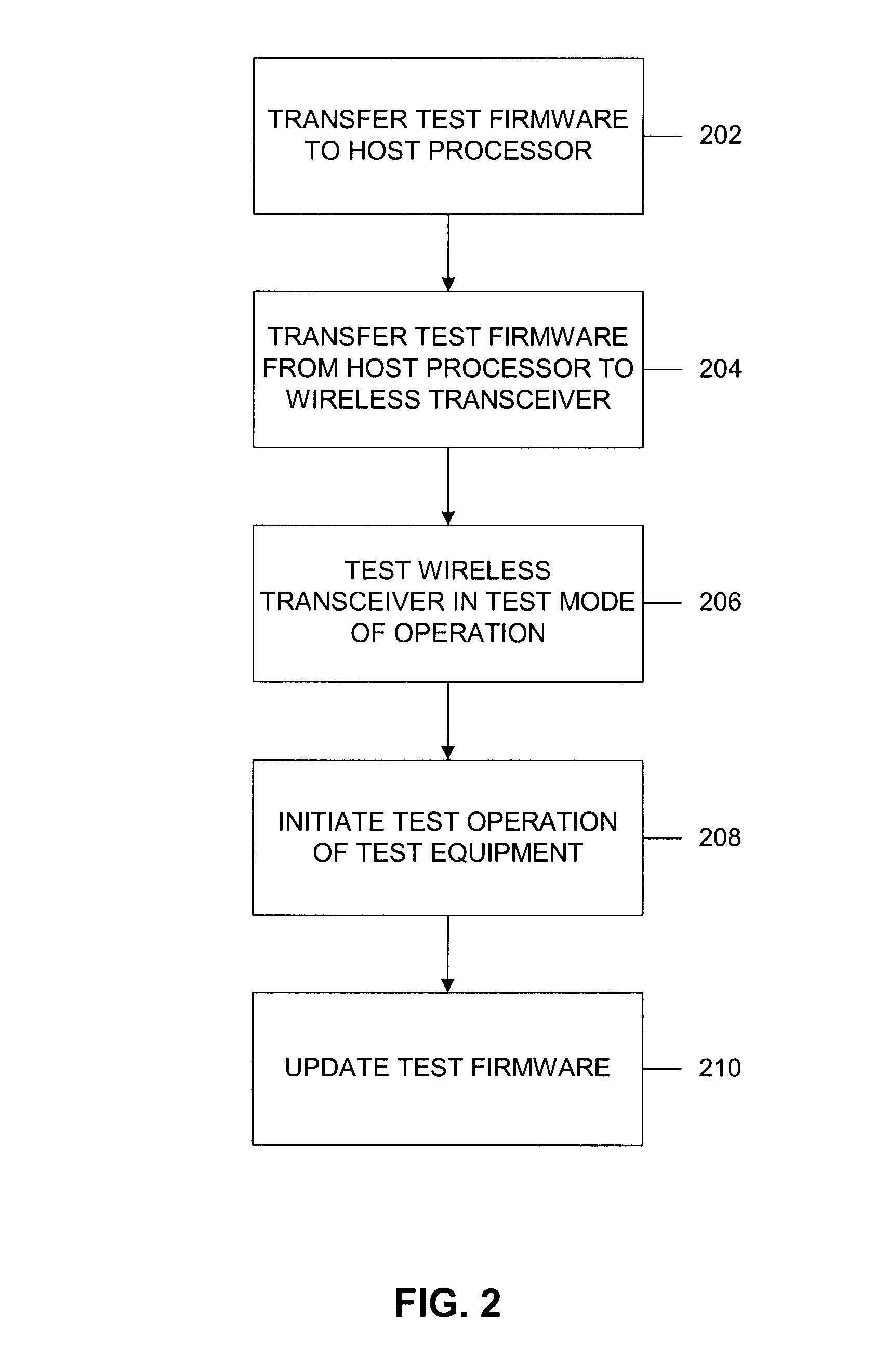
Accordingly, production testing becomes more complicated since testing firmware must be installed or stored for running on the embedded host processor.
While using firmware in an embedded processor may be acceptable for a single platform, this approach quickly becomes unacceptable when multiple platforms are involved and must be supported.
Accordingly, the manufacturer, while interested in producing a fully functional wireless transceiver capability, is nonetheless not interested in spending significant resources on integrating the wireless function in view of its limited role in the overall operation of the system.
This, however, is disadvantageous due to the fact that increasing the capture window will also slow down the overall data capture and analysis operation, since more data will need to be transferred between the capture memory and analysis engine.
Further, in many communication systems, the data packets are not closely spaced, which means that much of the captured data is unused since it corresponds to the gaps between consecutive data packets.

Method used


Image

  • Apparatus, System and Method for Calibrating and Verifying a Wireless Communication Device
  • Apparatus, System and Method for Calibrating and Verifying a Wireless Communication Device
  • Apparatus, System and Method for Calibrating and Verifying a Wireless Communication Device

Examples


Embodiment Construction

[0032]The following description of the embodiments is merely exemplary in nature and is in no way intended to limit the invention, its application, or uses. For purposes of clarity, the same reference numbers will be used in the drawings to identify similar elements. The embodiments are described in sufficient detail to enable one of ordinary skill in the art to practice the disclosure, and it will be understood that other embodiments may be practiced with some variations without departing from the spirit or scope of the subject invention.

[0033]As used herein, the term module, circuit and / or device refers to an Application Specific Integrated Circuit (ASIC), an electronic circuit, a processor (shared, dedicated, or group) and memory that execute one or more software or firmware programs, a combinational logic circuit, and / or other suitable components that provide the described functionality. Absent a clear indication to the contrary from the context, it will be understood that indiv...


PUM


Abstract

An apparatus for testing a wireless communication device includes a receiver, a capture module, and a control module. The receiver receives at least one test packet transmitted from the wireless communication device. The capture module captures at least a portion of the at least one test packet. The control module selectively controls the capture module to capture at least the portion based on a predetermined test flow. In one example, the at least one test packet is transmitted by the wireless communication device according to the predetermined test flow. In one example, control module selectively controls the capture module to capture at least the portion based on an expected calibration value associated with the at least one test packet. In one example, the control module selectively controls the capture module to capture at least the portion based on a predetermined value of interest.

Description

RELATED CO-PENDING APPLICATIONS[0001]This application is a continuation-in-part of U.S. patent application Ser. No. 11 / 279,778 filed on Apr. 14, 2006. This application is also related to co-pending U.S. patent application Ser. Nos. 11 / 422,475 and 11 / 422,489 filed on Jun. 6, 2006, which are hereby incorporated by reference in their entirety.BACKGROUND[0002]1. Field of the Invention[0003]The present disclosure relates to wireless communication systems, and more particularly to production testing of wireless communication systems.[0004]2. Related Art[0005]As the number and uses of wireless data communication systems increase, it has become increasingly important to the manufacturers of such systems to perform production testing of the wireless transceivers embedded in such systems in a more time-efficient manner. As is well known, a problem with production testing of such embedded transceivers is that no direct, e.g., wired, digital control connection is generally available between the...

Claims


Application Information

Patent Timeline
IPC IPC(8): H04L12/26
CPCH04B17/0085H04L12/2697H04B17/21H04W24/06H04W88/02H04L43/50
Inventor OLGAARD, CHRISTIAN VOLF
Owner LITEPOINT
Learn More