
Power converters

Active Publication Date: 2008-11-20
CONVERTEAM TECH LTD
View PDF14 Cites 28 Cited by
  • Summary
  • Abstract
  • Description
  • Claims
  • Application Information

AI Technical Summary

Benefits of technology

[0019]The first controller preferably supplies a control signal that varies in accordance with the prevailing motor conditions to the second controller. This control signal can then be used by the second controller to limit the level of power that is transferred to the dc link from the supply network through the second active rectifier / inverter. The control signal therefore prevents any more power being imported into the dc link through the second active rectifier / inverter when the motor has reached its physical performance limits (i.e. when the motor is already operating at its maximum shaft speed or its maximum rate of acceleration, for example).

Problems solved by technology

However, the mechanical load must normally retain sufficient energy (in the form of inertia, momentum etc.) to maintain operation during the time when it is not possible to obtain electrical power from the supply network.

Method used


Image

  • Power converters
  • Power converters
  • Power converters

Examples


Embodiment Construction

Power Converter Topology

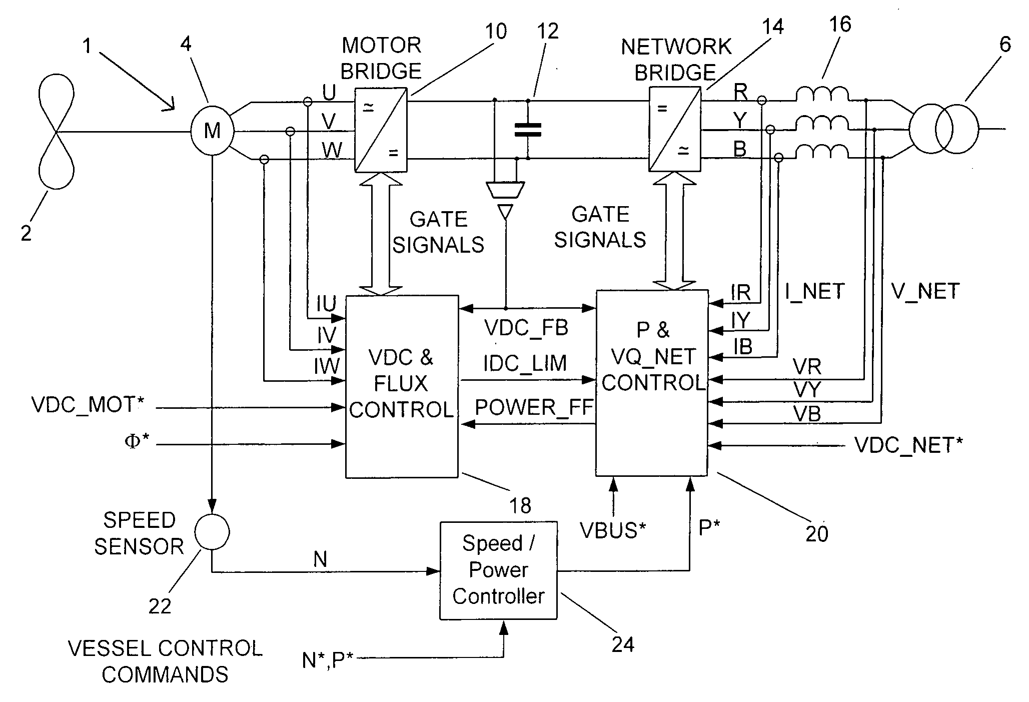
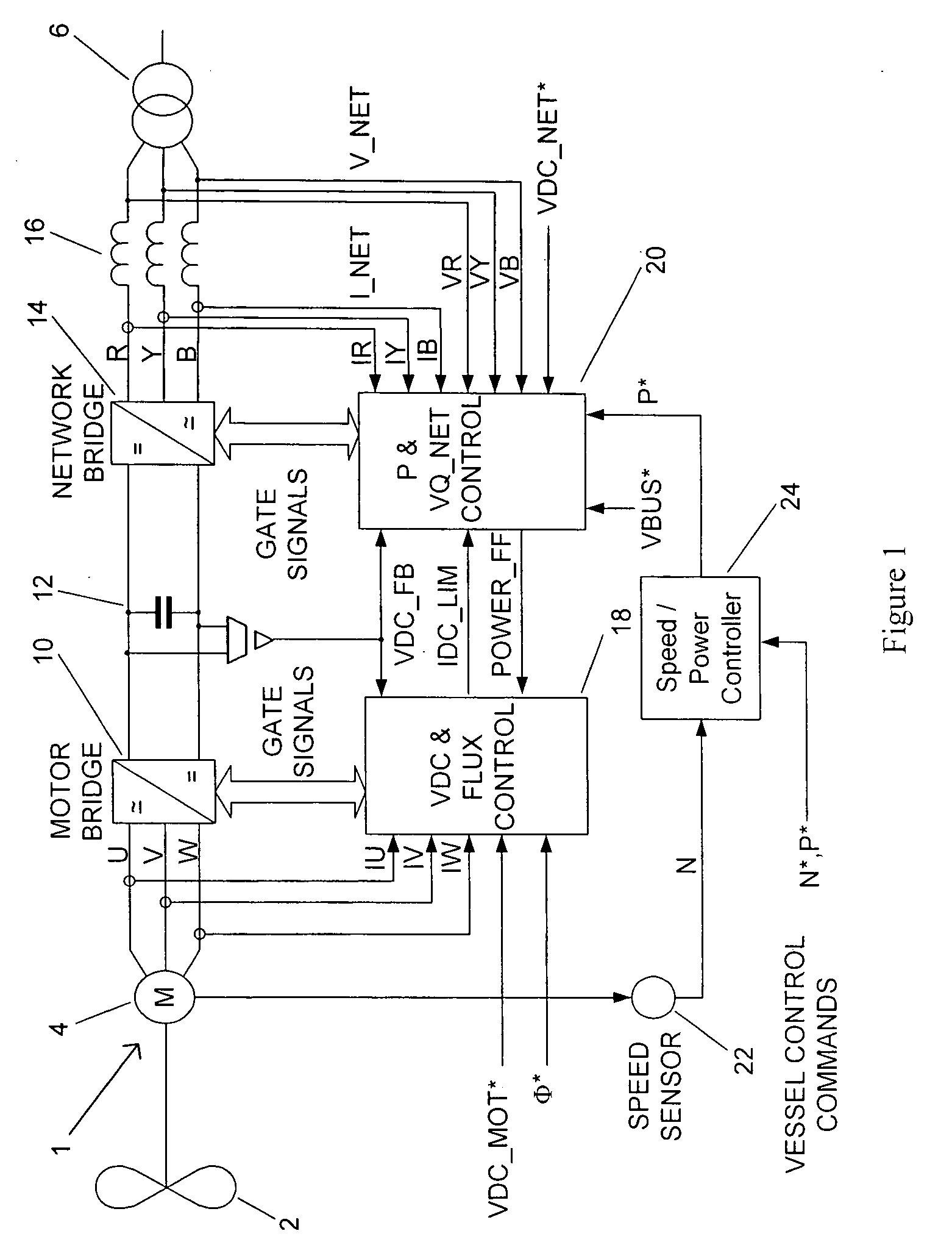
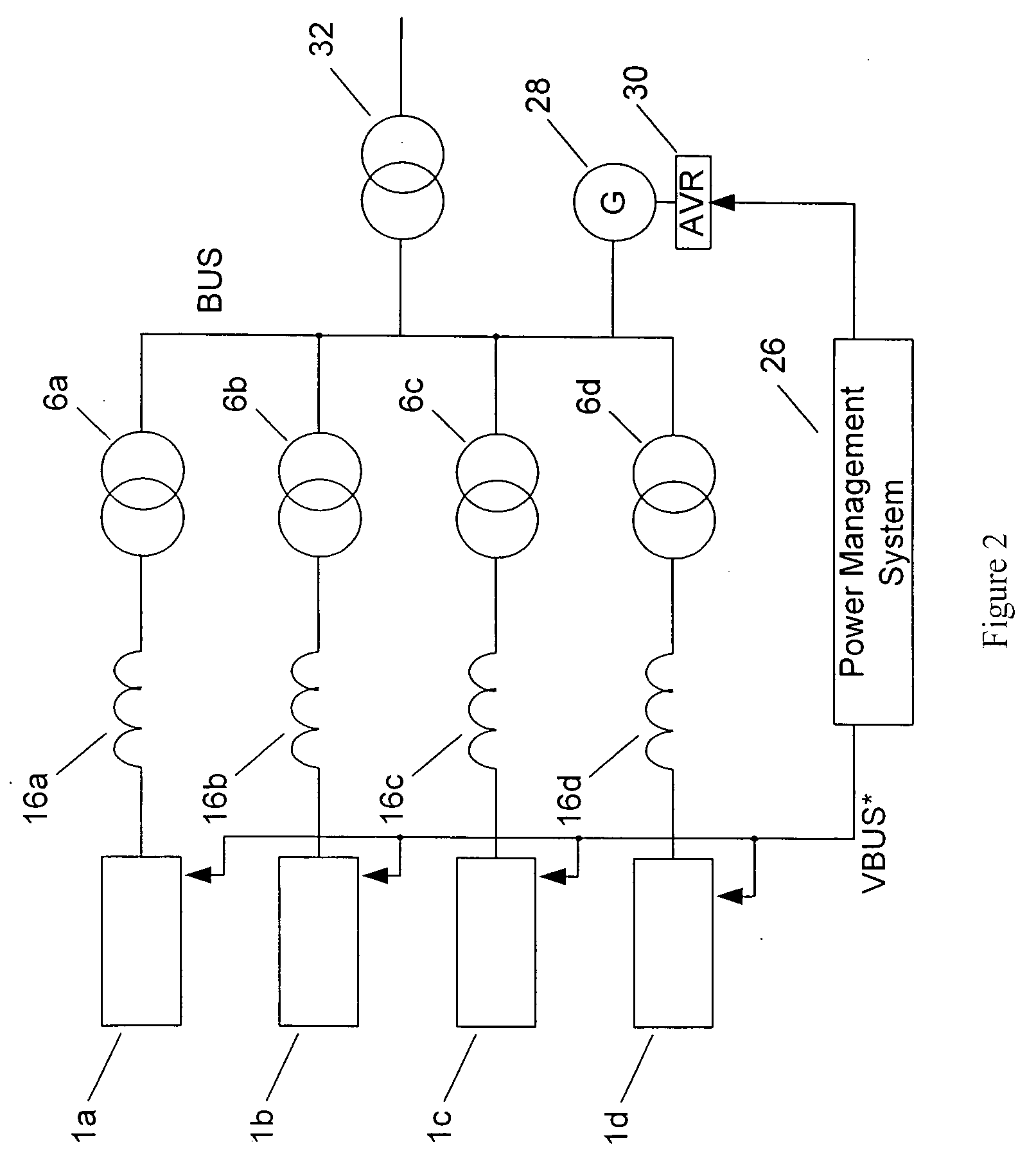
[0069]The basic topology of the power converter will be outlined with reference to FIGS. 1 and 2. Although the power converter is described below in the context of electric marine propulsion systems, it will be readily appreciated that other uses are possible. For example, the power converter can be used as part of a drive system for pumps, fans, compressors or other industrial type loads.

[0070]A propeller assembly 2 of an electric marine propulsion system is driven by the rotor (not shown) of a variable speed ac induction motor 4. The propeller assembly 2 will normally consist of a number of blades mounted on a rotating shaft with a fixed pitch. The rotating shaft may be directly connected to the rotor of the motor 4 or indirectly through a gearbox (not shown) that is used to adjust the shaft speed. The speed at which the propeller assembly 2 must rotate will depend on the speed of the marine vessel and the level or direction of thrust required for propulsio...


PUM


Abstract

The present invention is directed to a power converter that can be used to interface a motor 4 that requires variable voltage at variable frequency to a supply network (bus) providing a nominally fixed voltage and nominally fixed frequency. The power converter includes a first active rectifier / inverter 10 electrically connected to the stator of the motor 4 and a second active rectifier / inverter 14. Both the first and second active rectifier / inverters include a plurality of semiconductor power switching devices. A dc link 12 is connected between the first active rectifier / inverter and the second active rectifier / inverter. A filter 16 is connected between the second active rectifier / inverter and the supply network and includes network terminals. The power converter includes a first controller 18 for the first active rectifier / inverter and a second controller 20 for the second active rectifier / inverter. The first controller 18 uses a dc link voltage demand signal VDC_MOT* indicative of a desired dc link voltage to control the semiconductor power switching devices of the first active rectifier / inverter 10 to achieve the desired level of dc link voltage that corresponds to the dc link voltage demand signal. The second controller 20 uses a power demand signal P* indicative of the level of power to be transferred to the dc link 12 from the supply network (bus) through the second active rectifier / inverter 14, and a voltage demand signal VBUS* indicative of the voltage to be achieved at the network terminals of the filter 16 to control the semiconductor power switching devices of the second active rectifier / inverter 14 to achieve the desired levels of power and voltage that correspond to the power and voltage demand signals. The power converter can be employed in a marine propulsion system where the rotor of the motor 4 is used to drive a propeller assembly 2.

Description

FIELD OF THE INVENTION[0001]The present invention relates to power converters, and in particular to power converters that can be used to interface motors operating at variable voltage at variable frequency to a power grid or supply network at nominally fixed voltage and frequency. The present invention also includes features that allow the power converters to remain connected to the supply network and retain control during network fault and transient conditions. The power converters are particularly suitable for use with, but not restricted to, marine propulsion systems.BACKGROUND OF THE INVENTION[0002]The propeller assembly of a marine vessel typically rotates at variable speed, both in the forward and reverse directions. Where a marine vessel uses an electric power and propulsion system then the motor driving the propeller assembly will also need to operate at variable frequency (for the case where the propeller assembly is driven directly by the rotor of the motor then the freque...

Claims


Application Information

Patent Timeline
Patent Type & Authority Applications(United States)
IPC IPC(8): H02P27/06
CPCB63H21/17Y02T70/5236B63H23/24H02M5/271H02M5/4585H02M7/48H02P27/05
Inventor JONES, RODNEYNEWTON, CHRISTOPHER
Owner CONVERTEAM TECH LTD
Learn More