
Liquid sealed vibration isolating device

a liquid sealed and isolating device technology, applied in the direction of shock absorbers, machine supports, mechanical equipment, etc., can solve the problems of unstable support of the whole liquid sealed vibration isolating device, inability to generate partition members, and difficulty in assembling operation for fixing diaphragms while maintaining proper sealing properties. , to achieve the effect of reducing the frequency of rigid resonance, ensuring stability, and ensuring stability

Active Publication Date: 2008-11-20
YAMASHITA RUBBER CO LTD +1
View PDF2 Cites 27 Cited by
  • Summary
  • Abstract
  • Description
  • Claims
  • Application Information

AI Technical Summary

Benefits of technology

[0027]According to the invention as defined in the first aspect, since the partition member is floatingly supported between the insulator and the outer peripheral thick wall portion of the diaphragm, it is possible to reliably generate the rigid resonance by the partition member. Then, since the elastic body is interposed between the second metallic fitting and the partition member, the transmission of vibration from the partition member to the second metallic fitting can be blocked by this elastic body interposed layer in cooperation with the rigid resonance by the partition member. Therefore, even if the vibration due to the cavitation phenomenon in the primary liquid chamber is generated, the vibration is not transmitted from the second metallic fitting to the vehicle body, so that the generation of noise perceivable on the side of vehicle body can be prevented. Further, since the elastic supporting portion is provided on the outer peripheral thick wall portion of the diaphragm and the rigid metallic diaphragm support is united with the outer peripheral thick wall portion, the outer peripheral thick wall portion of the diaphragm can be securely supported through the metallic diaphragm support by the second metallic fitting so as to ensure the reliable support of the partition member by the elastic support portion, when the metallic diaphragm support is fixed by the second metallic fitting in the directly contacted relationship between these metallic members. Also, the device can be small-sized and the component parts can be similar to the conventional ones, thereby making it possible to save the cost. Moreover, when the second metallic fitting is fixedly mounted on the vehicle body side, the device can be steadily supported without lateral movement, etc.
[0040]According to the invention as defined in the twelfth aspect, since the mass comprising the hydraulic liquid in the secondary liquid chamber and the fitting ring is added to the mass of the rigid resonance, it is possible to decrease the frequency of the rigid resonance by the increase of the mass thereby to easily adjust the resonance frequency.

Problems solved by technology

However, since the whole of liquid sealed structure is subject to lateral movement, etc. due to deformation of the elastic body interposed in relation to the vehicle body fitting (bracket), the support of the whole of the liquid sealed vibration isolating device becomes unstable.
Moreover, since the device becomes large and component parts are increased so as to incur the increase in cost, the improvement in these respects is required.
Therefore, the partition member is not possible to generate and is not designed to generate the rigid resonance for effectively blocking for example the frequencies of about 800˜4000 Hz as a practically considerable range (hereinafter, referred to as noise frequency range) of the frequency which is perceived as the noise, within a frequency range of vibration generated due to the cavitation phenomenon.
Thus, since there is difficulty in the fitting operation of the diaphragm at the time of assembling, it is required to make the assembling operation easy.
Further, in the example of the patent reference 3, a seal portion formed by an outer peripheral portion of a diaphragm is subject to elastic deformation, so that an assembling operation for fixing the diaphragm while maintaining a proper sealing property becomes difficult.

Method used


Image

  • Liquid sealed vibration isolating device
  • Liquid sealed vibration isolating device
  • Liquid sealed vibration isolating device

Examples


first embodiment

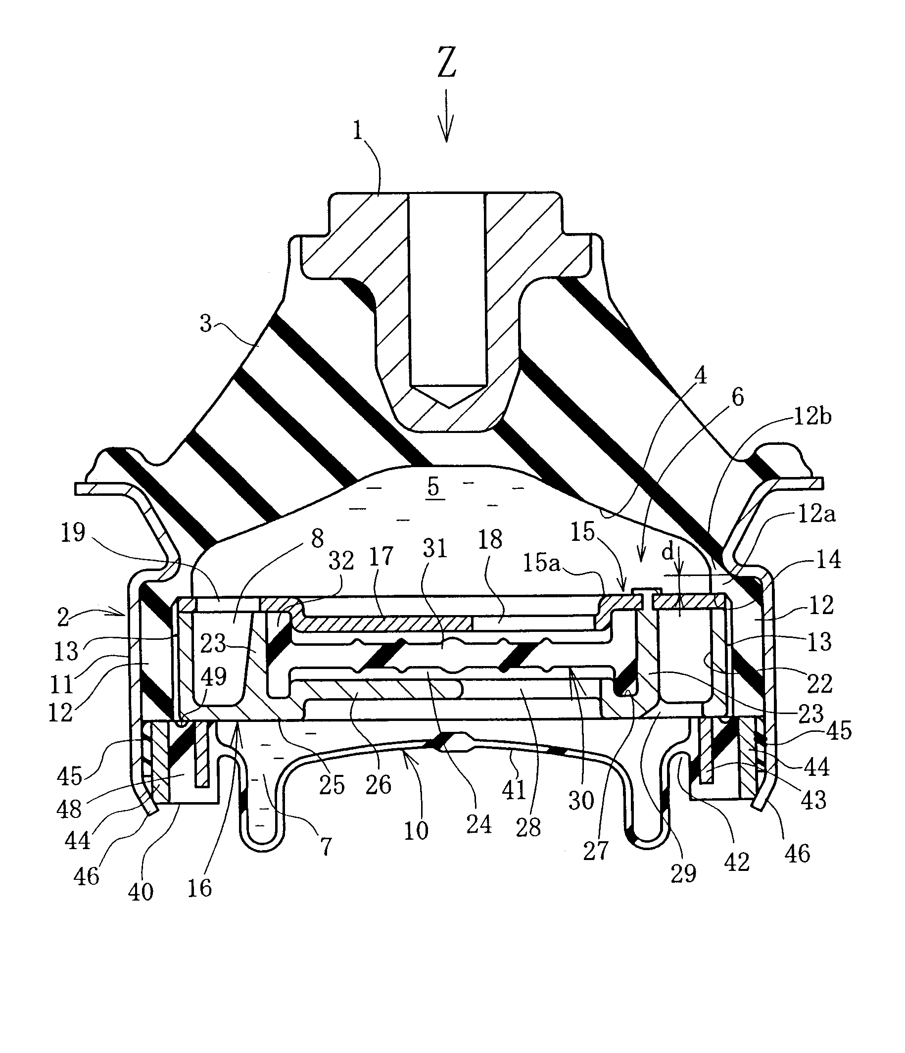
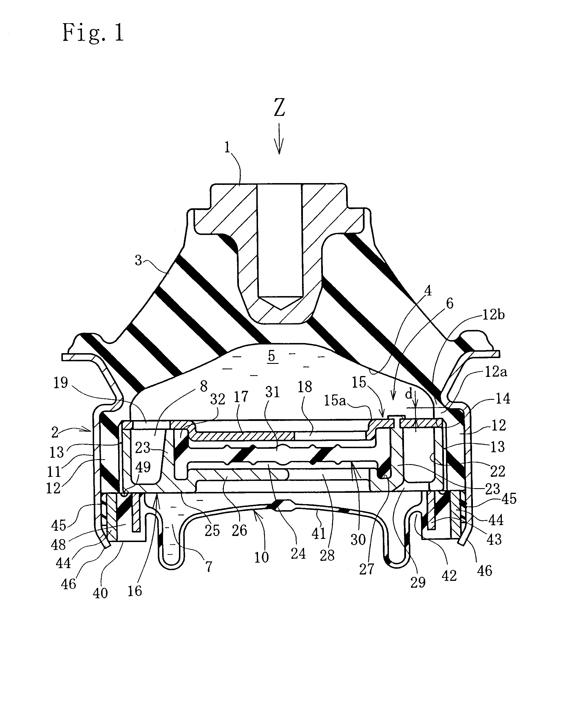
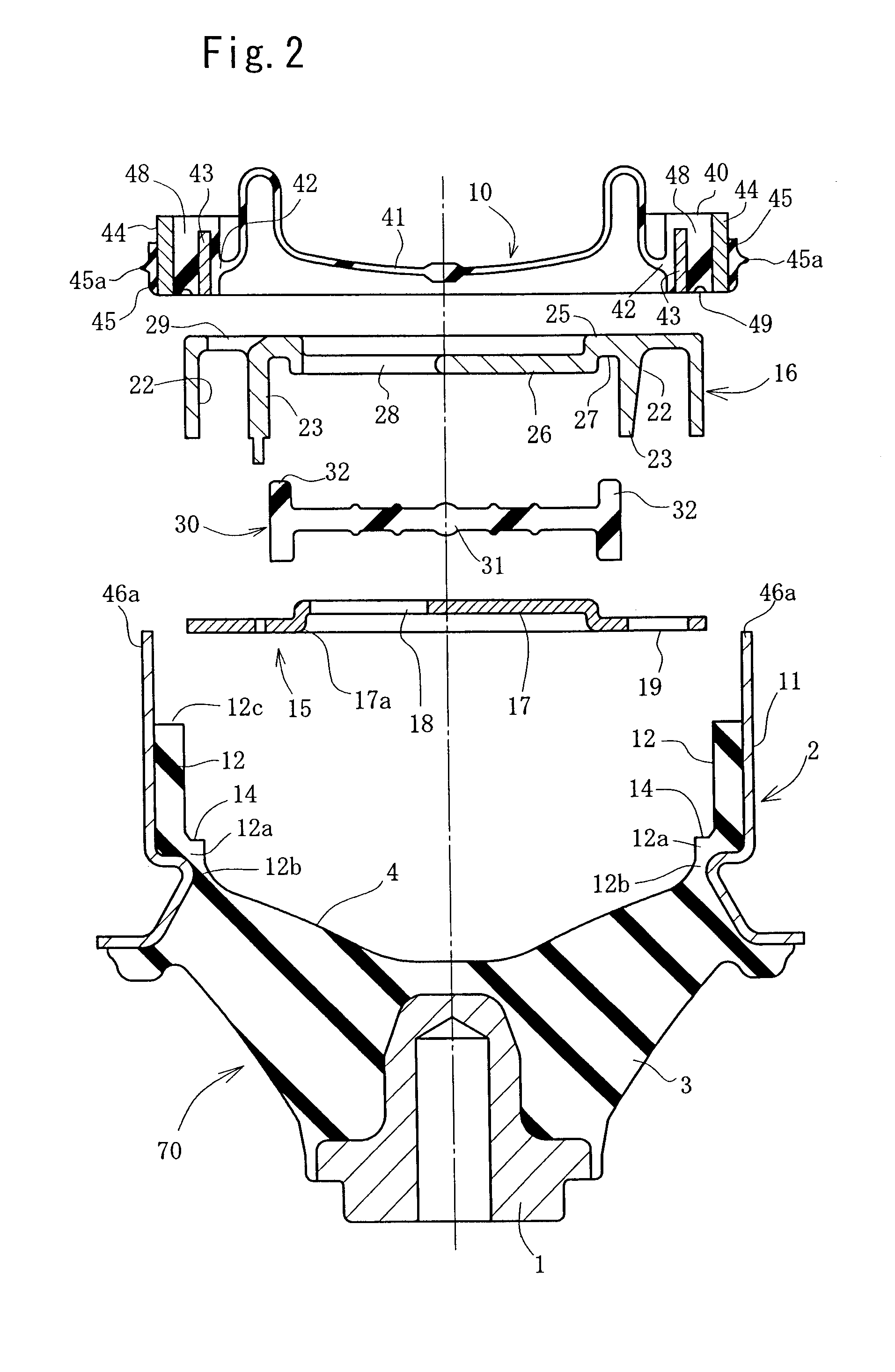
[0048]Hereinafter, the first embodiment embodied in an engine mount for motor vehicles will be explained with reference to the accompanying drawings. FIG. 1 is a longitudinal cross section of an engine mount. FIG. 2 is an exploded view of each component. FIG. 1 also is a cross section cut in the inputting direction Z of vibration. In the following explanation, each of directions such as up and down, right and left, or the like is expressed based on an illustrated state in FIG. 1.

[0049]In these drawings, this engine mount comprises a first metallic fitting 1 to be mounted on the side of an engine (not shown) of the vibration source, a second metallic fitting 2 forming a vehicle body side fitting to be mounted on a vehicle body, i.e., on the vibration receiving side, and an insulator 3 adapted to connect these two members. The insulator 3 is formed by a known vibration isolating elastic member such as rubber or the like and is an elastic body functioning as a main vibration isolating ...

second embodiment

[0087]FIG. 3 concerns the second embodiment and is a cross sectional view on an enlarged scale, similar to FIG. 1, showing the supporting structure of the partition member 6. In this embodiment, only the floating support structure for the partition member 6 is modified a little in comparison with the preceding embodiment. Therefore, the explanation will be focused on this modified structure, and with respect to other structure identical to the preceding embodiment, like parts are given like reference characters and the explanation will be omitted.

[0088]In this embodiment, an L-typed ring 50 in the shape of L in cross section is united with the outer peripheral thick wall portion 40. The L-typed ring 50 corresponding to the metallic diaphragm support of the present invention is provided with a vertical wall portion 51 and a bottom portion 52. The vertical wall portion 51 is inserted into the outer peripheral portion of the outer peripheral thick wall portion 40 and is arranged in the...

fourth embodiment

[0099]FIGS. 6 and 7 concern the present invention, wherein FIG. 6 is a longitudinal cross section of an engine mount, and FIG. 7 is an exploded view of each of components. FIG. 6 also is a cross section cut in the inputting direction Z of principal vibration. In this embodiment, with respect to the structure identical to the previously explained embodiments, like or corresponding parts are given like reference characters and the explanation will be partially omitted. Also, in the following explanation, each of directions such as up and down, right and left, or the like is expressed based on an illustrated state in FIG. 6.

[0100]Referring now to FIGS. 6 and 7, an outer periphery of the bottom portion 25 of the lower holder 16 is supported by an outer peripheral portion of the diaphragm 10. The outer peripheral portion of the diaphragm 10 is comprised of an outer peripheral thick wall portion 40 and a fitting ring 50. The outer peripheral thick wall portion 40 is a comparatively rigid ...


PUM


Abstract

To block the transmission to a vehicle body side of the vibration due to the cavitation phenomenon occurred in a primary liquid chamber so as to prevent the generation of noises, at the same time, to make the device compact, and to improve the fitting accuracy to obtain the reliable positioning, a first metallic fitting and a second metallic fitting are connected by an insulator. A primary liquid chamber and a secondary liquid chamber formed inwardly are partitioned by a partition member and communicated therebetween by an orifice passage. The partition member is floatingly supported between an extended portion of the insulator and an outer peripheral thick wall portion of a diaphragm, and the tuning is performed to generate the rigid resonance at the predetermined frequency. An outer ring is provided in the outer peripheral thick wall portion so as to be securely fixed by a fixing portion formed by bending an end of an outer cylindrical fitting. The floatingly supporting structure does not become large-sized and complicated since the partition member is simply floatingly supported.

Description

BACKGROUND OF THE INVENTION[0001]1. Field of the Invention[0002]The present invention relates to a liquid sealed vibration isolating device for use in an engine mount or the like for motor vehicles and more particularly, to the device capable of effectively reducing noises created due to a cavitation phenomenon.[0003]2. Description of the Related Art[0004]In the liquid sealed vibration isolating device of this type, negative pressure is developed instantaneously in a primary liquid chamber when the heavy load is applied, so as to cause the cavitation phenomenon that hydraulic liquid is partially vaporized, and then the noise is generated. In view of this, there are proposed various kinds of devices for reducing transmission of the noise. The vibration generated when bubbles due to the cavitation phenomenon burst is transmitted from a partition member to a second metallic fitting and then from the second metallic fitting to a vehicle body side, so that it is perceived as the noise.[0...

Claims


Application Information

Patent Timeline
IPC IPC(8): F16F13/00F16F5/00
CPCF16F13/105
Inventor SAITO, JUNNISHIZAKA, MASATOMOKUBO, NOBUOYANAGASE, HIROSHI
Owner YAMASHITA RUBBER CO LTD
Learn More