
Method of Controlling a Turbocharger Having a Variable-Geometry Mechanism and a Waste Gate

a technology of variable geometry and waste gate, which is applied in the direction of machines/engines, hot gas positive displacement engine plants, combustion engines, etc., can solve the problems of reducing the efficiency of the turbocharger and the difficult control of the variable geometry mechanism, so as to reduce the amount of flow disturbance and reduce the pressure of the exhaust gas

Active Publication Date: 2008-11-20
GARRETT TRANSPORATION I INC
View PDF10 Cites 11 Cited by
  • Summary
  • Abstract
  • Description
  • Claims
  • Application Information

AI Technical Summary

Benefits of technology

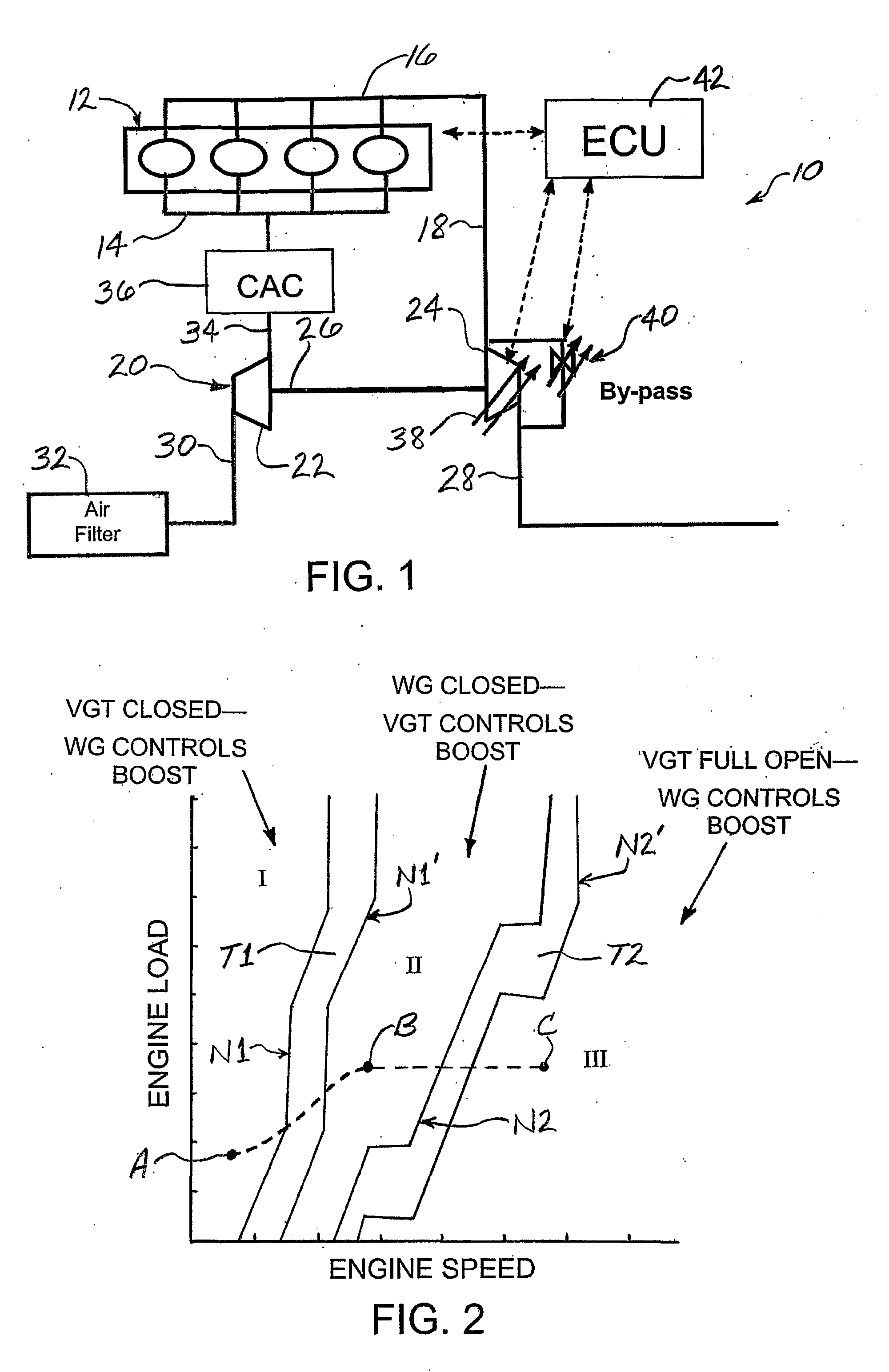
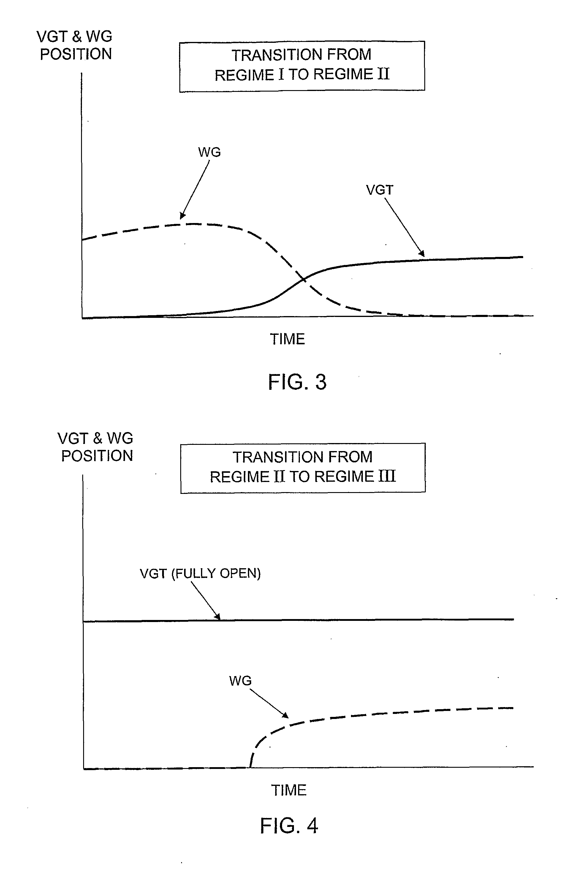
[0006]In preferred embodiments of the invention, there is a transition region between the low-speed regime and the intermediate-speed regime. As speed increases through the transition region such that the variable-geometry mechanism is to be opened, the waste gate is positioned in a relatively open position and the variable-geometry mechanism begins to open while simultaneously the waste gate begins to close. It is thought that the open position of the waste gate reduces the pressure of the exhaust gas in the chamber and thereby reduces the amount of flow disturbance that occurs as the variable-geometry mechanism begins to open.

Problems solved by technology

The variable-geometry mechanism can be difficult to control at the very beginning of the opening process.
When the mechanism is opened just slightly from its fully closed position, it can create a significant amount of disturbance in the exhaust gas flow into the turbine, thereby decreasing efficiency of the turbocharger.

Method used


Image

  • Method of Controlling a Turbocharger Having a Variable-Geometry Mechanism and a Waste Gate
  • Method of Controlling a Turbocharger Having a Variable-Geometry Mechanism and a Waste Gate
  • Method of Controlling a Turbocharger Having a Variable-Geometry Mechanism and a Waste Gate

Examples


Embodiment Construction

[0014]The present inventions now will be described more fully hereinafter with reference to the accompanying drawings, in which some, but not all embodiments of the inventions are shown. Indeed, these inventions may be embodied in many different forms and should not be construed as limited to the embodiments set forth herein; rather, these embodiments are provided so that this disclosure will satisfy applicable legal requirements. Like numbers refer to like elements throughout.

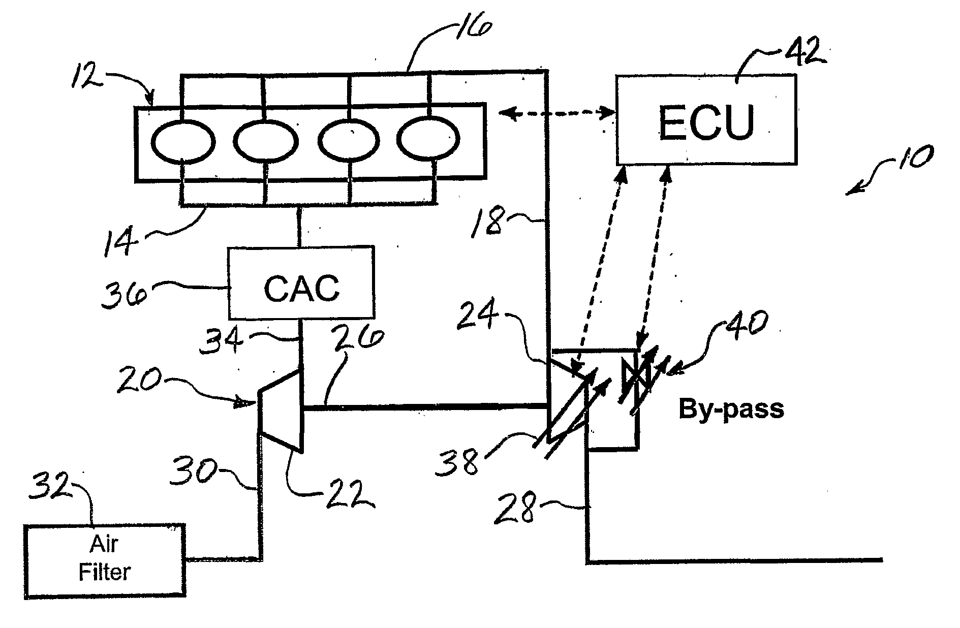
[0015]An engine and turbocharger system 10 in accordance with one embodiment of the invention is depicted in diagrammatic fashion in FIG. 1. The system comprises an internal combustion engine 12 that is supplied with a mixture of fuel and air via an intake manifold 14 and exhausts the products of combustion, referred to as “exhaust gas”, via an exhaust manifold 16. In a popular alternate arrangement, fuel can be supplied directly to each cylinder, though this will not affect the applicability of the present in...


PUM


Abstract

A method for controlling a variable-geometry turbine (24) that includes a variable-geometry mechanism that is movable between a fully closed position closing a relatively greater portion of the turbine nozzle and a fully open position closing a relatively smaller portion of the nozzle. The turbine (24) further comprises a waste gate (40) movable between a closed position and an open position in which some of the exhaust gas bypasses the turbine (24). At low engine speeds, turbocharger boost us regulated by regulating the position of the wastegate. At high engine speeds, the variable geometry is fully open and the wastegate is opened again. When at medium engine speeds, the variable geometry mechanism is to be moved from its closed position toward its fully open position, the waste gate (40) is in an open position to cause a proportion of the exhaust gas to bypass the turbine (24) and thereby reduce the pressure of the exhaust gas in the chamber. While this reduced pressure of the exhaust gas is in effect, the variable-geometry mechanism is moved from the fully closed position toward the fully open position while simultaneously the waste gate begins to close.

Description

BACKGROUND OF THE INVENTION[0001]The present invention relates to turbochargers having a variable-geometry mechanism for regulating the flow area of the nozzle leading into the turbine, and having a waste gate for causing exhaust gas to bypass the turbine under certain conditions.[0002]In turbochargers of the above-described type, the variable-geometry mechanism (which can comprise a sliding piston or slide vane, or variable vanes in the nozzle, or the like) is typically movable between a fully closed position and a fully open position. In the fully closed position, the nozzle is significantly closed (and in some cases completely closed) by the mechanism. In the fully open position of the piston, the nozzle is significantly open (and in some cases completely open).[0003]The variable-geometry mechanism can be difficult to control at the very beginning of the opening process. When the mechanism is opened just slightly from its fully closed position, it can create a significant amount ...

Claims


Application Information

Patent Timeline
IPC IPC(8): F02B37/12F02B37/22F02B37/18
CPCF02B37/12F02B37/18F02B37/22Y02T10/144Y02T10/12
Inventor FERRARI, SEBASTIANMASSART, EDUARDOLOMBARD, ALAINMITKA, JEROME
Owner GARRETT TRANSPORATION I INC
Learn More