
Manufacturing method of film insert molded article

Active Publication Date: 2008-11-13
SANWA SCREEN
View PDF6 Cites 43 Cited by
  • Summary
  • Abstract
  • Description
  • Claims
  • Application Information

AI Technical Summary

Benefits of technology

[0007]An object of the present invention is to provide a manufacturing method of the film insert molded article in which such disadvantages are dissolved and a resin layer is seen in the front and no wrinkle is generated in the film on the surface of the film insert molded article coated with the film even when dispersion is generated in the heat shrinking amount due to the thermoforming of the film.
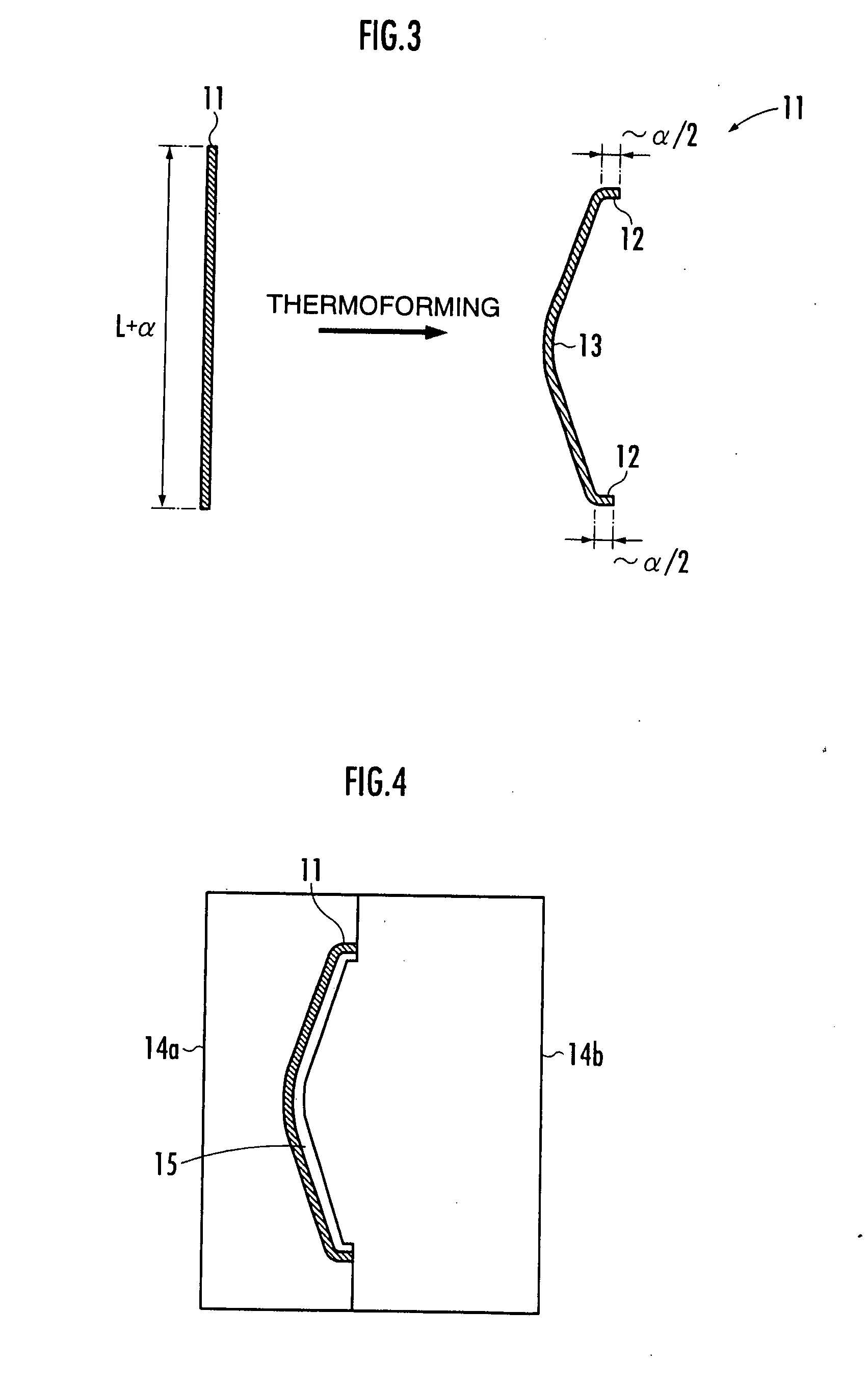
[0012]Next, the film for coating in which the three-dimensional shape and the outer circumferential bending portion are formed, is arranged within the cavity of the injection molding die such that the binder layer comes into contact with molten resin. The molten resin is then injected into the cavity. Thus, the molten resin filled within the cavity is cooled and solidified so that the injection-molded article of a shape formed along an shape of the inner plane of the cavity can be obtained. Further, since the binder layer is melted by heat of the molten resin and becomes an adhesive layer, the film for coating is molded integrally with the injection-molded article through the adhesive layer. As a result, it is possible to obtain the film insert molded article in which the coating plane is coated with the film for coating.
[0013]At this time, the film for coating has the outer circumferential bending portion and a size sufficient to coat the coating plane of the film insert molded article. Accordingly, it is possible to prevent a resin layer from being seen from the front of the coating plane. Further, since the film for coating has the outer circumferential bending portion, no excessive portion is generated in a portion for coating the coating plane when the film for coating is arranged within the die. Accordingly, it is possible to prevent a wrinkle from being generated in the film on the coating plane.
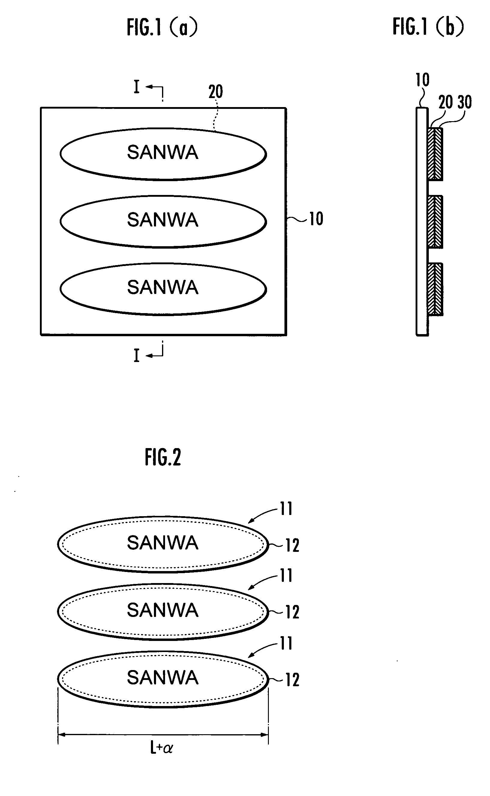
[0015]In accordance with study of the present inventors, the heat shrinkage due to the thermoforming of the film for coating lies within 1% of a maximum width of the film for coating, and variation in the heat shrinking amount lies within ±10% with respect to the heat shrinking amount. Therefore, in the manufacturing method of the present invention, the outer circumferential bending portion of the film for coating preferably has a width (α) of 1.1% or more of the maximum width (L) of the coating plane. In accordance with such a construction, the outer circumferential bending portion arranged in the outer circumferential side portion of the coating plane can be formed in the film for coating after the thermoforming even when the heat shrinkage due to the thermoforming of the film for coating becomes the largest. Thus, it is possible to reliably prevent a resin layer from being seen in the front on the coating plane.

Problems solved by technology

However, when the product size of the film insert molded article is increased, variation in the heat shrinking amount is also increased.
Accordingly, there are disadvantages in that the actual heat shrinking amount becomes larger than the predicted heat shrinking amount, and no entire surface of the keyboard panel can be coated with the film for coating, and a resin layer is seen in the front in some cases.
Further, when the actual heat shrinking amount is reversely smaller than the predicted heat shrinking amount, there are disadvantages in that an excessive portion is generated in the film for coating arranged within the die, and a wrinkle is generated in the film when the surface of the film insert molded article is coated.

Method used


Image

  • Manufacturing method of film insert molded article
  • Manufacturing method of film insert molded article
  • Manufacturing method of film insert molded article

Examples


Embodiment Construction

[0027]An embodiment of the present invention will next be explained in further detail with reference to the accompanying drawings.

[0028]First, as shown in FIG. 1, printing is performed on the rear surface of a plastic film 10 as a raw material so that a printing ink layer 20 is formed. In the plastic film 10, multicavity moulding is normally performed and a plurality of printing ink layers 20 are formed at a predetermined interval on the rear face of the plastic film 10.

[0029]A film made from polyethylene terephthalate resin is preferably used as the plastic film 10 since it is excellent in aptitude with respect to printing, thermoforming property or the like. However, a film constructed by other resins such as polycarbonate resin or the like may be also used. The above printing can be performed by a silk screen method or an offset method. A color number of ink forming the printing ink layer 20 can be suitably determined by a design of the film insert molded article as a product.

[00...


PUM

PropertyMeasurementUnit
Temperatureaaaaaaaaaa
Fractionaaaaaaaaaa

Abstract

A manufacturing method of a film insert molded article in which no resin layer is seen in the front and no wrinkle is generated in a film is provided. A thermoformed film (11) for coating is arranged within a cavity (15), and molten resin is injected so that a film insert molded article (50) molded integrally with the film (11) for coating and having a coating plane coated with the film (11) for coating is obtained. A printing ink layer (20) and a binder layer (30) are formed in a raw material film (10). The raw material film (10) is cut out and the film (11) for coating is formed so as to have a size for coating the coating plane and being able to form an outer circumferential bending portion (12) arranged in an outer circumferential side portion (41) by adding a width exceeding a heat shrinking amount of the film. After the film (11) for coating is preheated, the film (11) for coating is thermoformed so that a predetermined three-dimensional shape (13) and the outer circumferential bending portion (12) are formed. The film (11) for coating in which the three-dimensional shape (13) and the outer circumferential bending portion (12) are formed, is arranged within the cavity (15) such that the binder layer (30) comes into contact with molten resin. The molten resin is then injected.

Description

FIELD OF THE INVENTION[0001]The present invention relates to a manufacturing method of a film insert molded article.BACKGROUND ART[0002]A film insert molded article in which a film printing a pictograph, a mark, a design or the like thereon is molded integrally with an injection-molded article is formerly known as one of decorating techniques of the injection-molded article.[0003]For example, the film insert molded article is manufactured as follows (see Japanese Patent Laid-Open No. 63-34814). Namely, a decorating film having a display section of a keyboard printed on a face of the front side of a synthetic resin film able to be thermoformed is thermoformed in a shape of a surface of a keyboard panel so that a film for coating is made. The film for coating is then arranged within a die, and molten resin is injected from a rear side of the film for coating into the die so that the film insert molded article is manufactured.[0004]In the above former manufacturing method of the film i...

Claims


Application Information

Patent Timeline
IPC IPC(8): B29C39/12
CPCB29C45/14688B29C45/14811B29C2045/14704B29K2715/006
Inventor HAYASHI, SEIJIMATSUOKA, KIYOMIGOTO, YOSHIHIDEGOTO, EIICHIRO
Owner SANWA SCREEN
Learn More