Methods and systems for reducing carbon dioxide in combustion flue gases

a technology of combustion flue gas and carbon dioxide, which is applied in the direction of liquid degasification, combustion types, separation processes, etc., can solve the problems of increasing the footprint of scrubbers and strippers, increasing capital costs, operating costs, and energy consumption, and increasing energy consumption and costs

Inactive Publication Date: 2008-11-13
BHA ALTAIR
View PDF15 Cites 74 Cited by
  • Summary
  • Abstract
  • Description
  • Claims
  • Application Information

AI Technical Summary

Problems solved by technology

Such known impurities may cause foaming of the liquid and / or liquid degradation due to irreversible reactions with the impurities.
The scrubber footprint and stripper regeneration energy increases capital cost, operating costs, and energy consumption.
The additional flue gas processing and compression further increase energy consumption and costs.

Method used


Image

  • Methods and systems for reducing carbon dioxide in combustion flue gases
  • Methods and systems for reducing carbon dioxide in combustion flue gases
  • Methods and systems for reducing carbon dioxide in combustion flue gases

Examples


Embodiment Construction

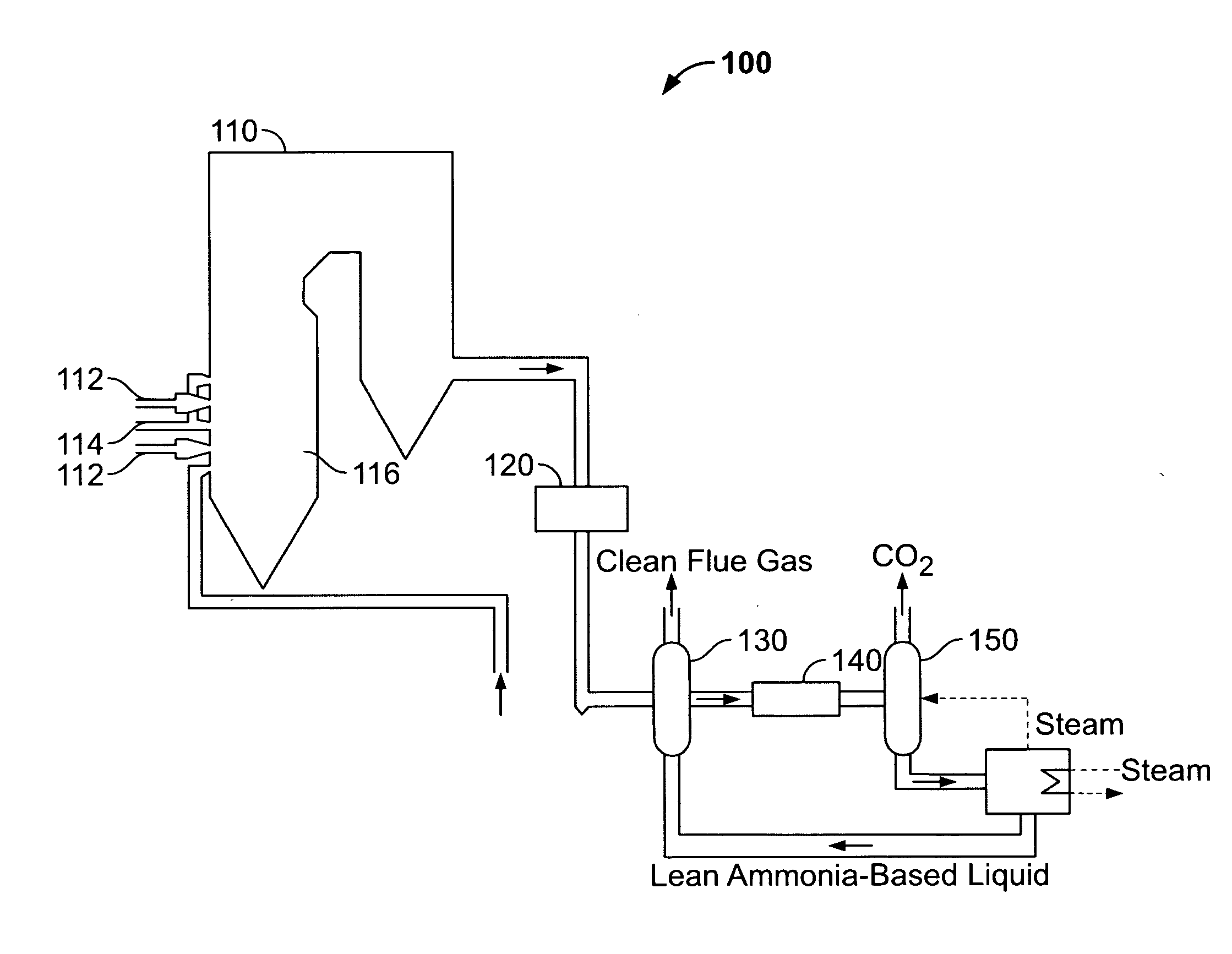
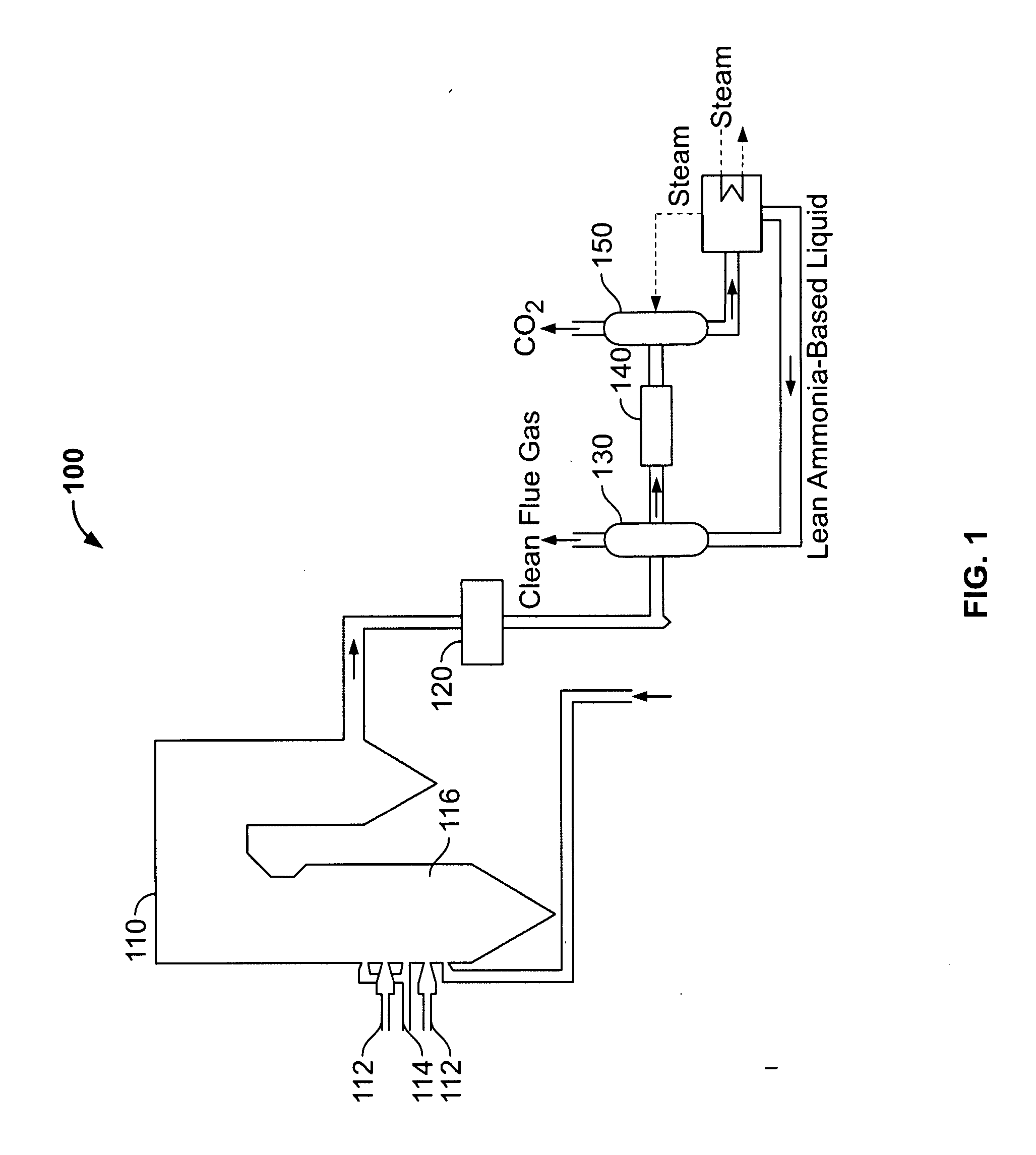
[0012]The exemplary methods and systems described herein overcome the disadvantages of known post-combustion carbon separation technologies by combining ammonia-based chemical absorption processes and hydrophobic membrane contactors.

[0013]FIG. 1 is a schematic diagram of an exemplary combustion system 100 that includes a furnace / boiler 110, optional pollution control devices 120, a CO2 absorber (scrubber) 130, a preheater 140, a desorber (stripper) 150, and a steam generator 160. Furnace / boiler 110 serves as a combustion chamber that includes fuel injection ports 112, air injection ports 114, and a combustion zone 116. In the exemplary embodiment, at least one fuel injection port 112 and at least one air injection port 114 are coupled to furnace / boiler 110 to inject fuel and air, respectively, into combustion zone 116.

[0014]After combustion of the fuel, a generated combustion exhaust gas, also known as a combustion flue gas, is optionally channeled in a transport stream into polluti...


PUM

PropertyMeasurementUnit
hydrophobicaaaaaaaaaa
volumeaaaaaaaaaa
sizesaaaaaaaaaa

Abstract

A method for processing flue-gas, in an exemplary embodiment, includes providing an absorber unit having a membrane contactor, channeling a combustion flue gas along a first surface of the membrane contactor, and channeling an ammonia-based liquid reagent along a second opposing surface of the membrane contactor. The method also includes partially separating the ammonia-based liquid from the flue gas such that the ammonia-based liquid and the flue gas contact at gas-liquid interface areas, defined by a plurality of pores of the membrane contactor, to separate CO2 from the flue gas by a chemical absorption of CO2 within the ammonia-based liquid to produce a CO2-rich ammonia-based liquid.

Description

BACKGROUND OF THE INVENTION[0001]This invention relates generally to industrial combustion systems, and more particularly to methods and systems for removing carbon dioxide (CO2) from combustion flue gases.[0002]At least some known carbon separation technologies intervene at different points in coal and / or natural gas systems. For example, carbon separation technologies that separate CO2 from combustion flue gases are generally known as post-combustion carbon separation technologies. Known post-combustion carbon separation technologies include processes such as, but not limited to, physical absorption, cryogenic separation, solid sorbent separation, chemical looping combustion, chemical absorption, and / or membrane separation.[0003]Some known chemical absorption processes attempt to remove CO2 from the flue gases by an exothermic reaction of CO2 with separation solvents, for example, potassium carbonate, sodium hydroxide, and amine-based solvents. Known amine-based liquids may includ...

Claims


Application Information

Patent Timeline
Patent Type & Authority Applications(United States)
IPC IPC(8): F01N3/04B01D19/00B01D47/00B01D53/14
CPCB01D53/1475B01D53/18B01D53/62B01D2251/2062Y02C10/04Y02C10/06Y02C10/10B01D61/00Y02E20/32Y02A50/20Y02C20/40B01D53/14B01D53/22B01D53/78F23G7/06F23J15/00
Inventor MOLAISON, JENNIFER LYNNSMITHIES, ALAN
Owner BHA ALTAIR
Why Eureka
Try Eureka