
Battery cell having energy control device

a battery cell and energy control technology, applied in the field of battery packs, can solve the problems of excessive voltage damage to active materials, temperature of the battery to increase to an unacceptable level, and thermal detection is not a likely candidate for lithium batteries, etc., to achieve efficient packaging characteristics, eliminate connecting hardware, and reduce weight

Inactive Publication Date: 2008-11-06
ENERDEL
View PDF3 Cites 13 Cited by
  • Summary
  • Abstract
  • Description
  • Claims
  • Application Information

AI Technical Summary

Benefits of technology

[0011]An advantage of the present invention is to provide a battery assembly having efficient packaging characteristics by integrating a device (the LEC) in each cell.
[0012]Another advantage of the present invention is to provide a battery assembly that reduces the weight by eliminating connecting hardware.
[0013]Still another advantage of the present invention is to provide a battery assembly that reduces manufacturing costs due to simplified assembly pattern

Problems solved by technology

Excessive voltage may damage the active materials.
In addition, overheating may occur as a result of prolonged overcharging of a battery causing the temperature of the battery to increase to an unacceptable level, possibly causing damage.
Thermal detection is not a likely candidate for lithium batteries however, because heat generated by charging lithium batteries may follow overcharge, rather than heat generation preceding the overcharge.
Therefore, a thermal protection circuit for a lithium battery is unpredictable and unreliable.
There are disadvantages to this approach.
For example, such software systems are unreliable as inaccurate readings can sometimes occur.
Alluding to the above, the aforementioned prior art designs fail to provide an important backup protection mechanism where a primary control, for example, a battery control unit (BCU), fails to control the charging as desired and are too complex and bulky in its form thereby negatively affecting packaging characteristics of the battery cell and packs in general

Method used


Image

  • Battery cell having energy control device
  • Battery cell having energy control device
  • Battery cell having energy control device

Examples


Embodiment Construction

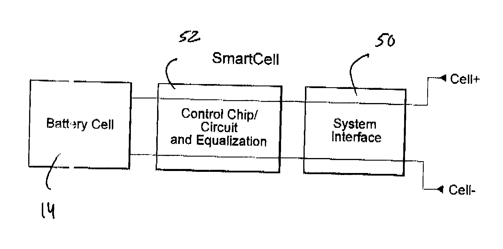
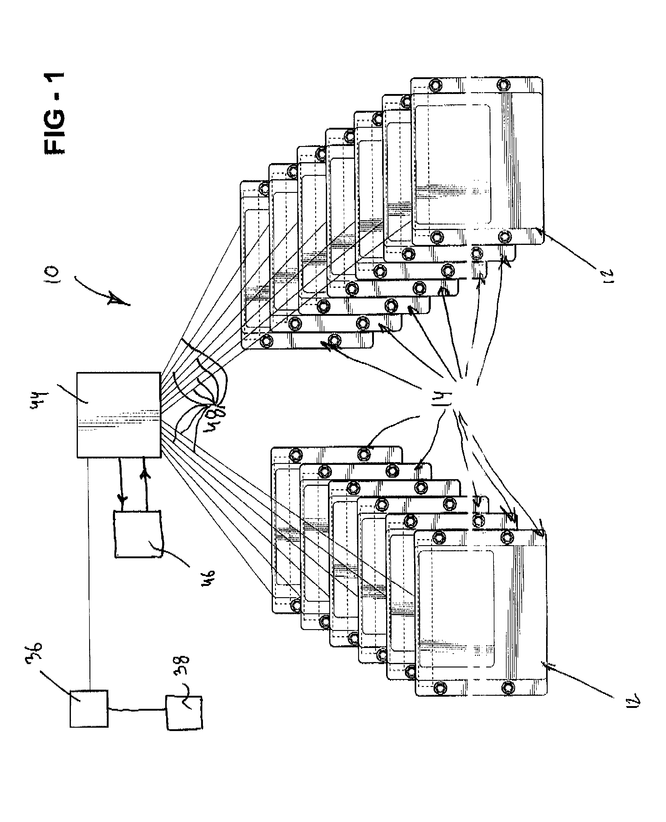
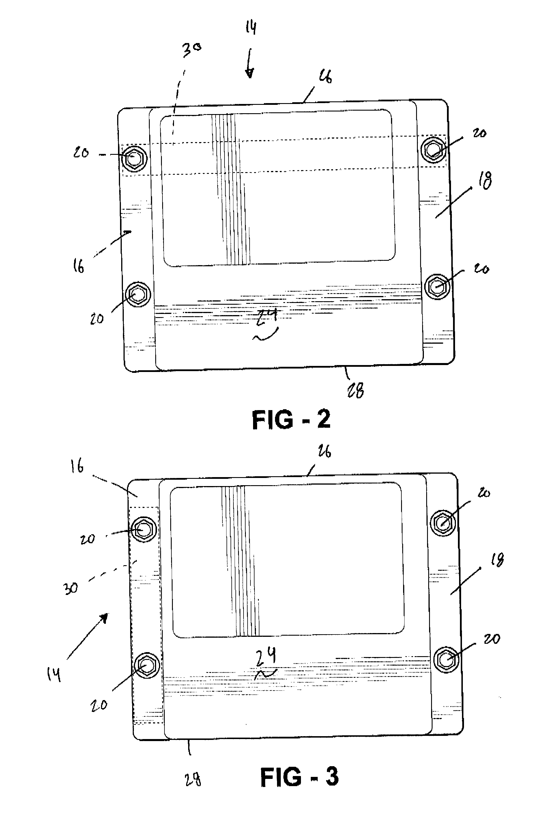
[0023]Referring to the Figures, wherein like numerals indicate like or corresponding parts, a battery assembly or a battery pack of the present invention is generally shown at 10. Preferably, the battery pack 10 includes several rows, generally indicated at 12, (only two shown in FIG. 1 for illustrative purposes without limiting the scope of the present invention) of battery cells (the cell), generally indicated at 14 and interconnected with one another in the pattern known to those skilled in the battery art. The battery pack 10 of the present invention is adaptable to be utilized in various configurations including and not limited to an overlapping battery cell packaging configuration, a vertical stack battery cell packaging configuration, and other configurations without limiting the scope of the present invention.

[0024]Each cell 14 includes a plurality of battery core components co-acting between one and the other to conduct electrolyte therebetween as known to those skilled in ...


PUM

PropertyMeasurementUnit
electrochemically conductiveaaaaaaaaaa
currentaaaaaaaaaa
voltageaaaaaaaaaa

Abstract

A battery assembly includes a plurality of battery cells. Each cell includes a plurality of first electrodes and second electrodes. First and second insulators extend over the first and second electrodes. An envelope or shell extends over the first and second insulators thereby encapsulating the first and second insulators. A lithium energy control electronics device (the LEC) is disposed, i.e. integrated inside the shell of each cell of the battery assembly. Each cell of the battery assembly is electronically and operatively communicated with one another through the respective LEC disposed inside each cell.

Description

RELATED APPLICATIONS[0001]This non-provisional application claims priority to a provisional application Ser. No. 60 / 806,050 filed on Jun. 28, 2006 and incorporated by reference herein in its entirety.FIELD OF THE INVENTION[0002]The subject invention relates to battery packs, and more particularly to a battery cell of the battery pack.BACKGROUND OF THE INVENTION[0003]Motor vehicles, such as, for example, hybrid vehicles use multiple propulsion systems to provide motive power. This hybrid vehicles recharge their batteries by capturing kinetic energy via regenerative braking. When cruising or idling, some of the output of the combustion engine is fed to a generator (merely the electric motor(s) running in generator mode), which produces electricity to charge the batteries. This contrasts with all-electric cars which use batteries charged by an external source such as the grid, or a range extending trailer. Nearly all hybrid vehicles still require gasoline as their sole fuel source thou...

Claims


Application Information

Patent Timeline
Patent Type & Authority Applications(United States)
IPC IPC(8): H01M6/42
CPCH01M6/42H01M10/4257H01M10/4207Y02E60/10
Inventor DIXON, JEFFHARTZOG, CHADYUMOTO, HIROYUKI
Owner ENERDEL
Learn More