Refrigerant evaporator

a technology of refrigerant evaporator and liquid refrigerant, which is applied in the direction of refrigerating machines, stationary conduit assemblies, lighting and heating apparatus, etc., can solve the problems of difficult to clear the stagnation of liquid refrigerant, and liquid refrigerant is likely to stagnate in the core, so as to reduce heat capacity, suppress the decrease of heat exchange efficiency, and increase the pressure loss

Inactive Publication Date: 2008-11-06
DENSO CORP
View PDF10 Cites 9 Cited by
  • Summary
  • Abstract
  • Description
  • Claims
  • Application Information

AI Technical Summary

Benefits of technology

[0008]In the above construction, since the width of the core is equal to or greater than 220 mm, an increase in pressure loss is slight and a decrease in heat exchange efficiency is suppressed. Although heat capacity is reduced due to the reduction of the thickness of the core, since the core has the width equal to or greater than 220 mm and the first upward path, which is the furthest from the refrigerant inlet in the paths provided by the tubes of the first row, has the width equal to or less than 95 mm, stagnation of the liquid refrigerant around a lower portion of the first upward path is easily cleared.

Problems solved by technology

In a case where such a refrigerant evaporator is employed to a refrigerant cycle apparatus, liquid refrigerant is likely to stagnate in the core due to the lack of heat capacity when an operation of a refrigerant compressor of the refrigerant cycle apparatus is transferred from an ON state to an OFF state.
Also, it is difficult to clear the stagnation of the liquid refrigerant even after the refrigerant compressor switched to the ON state.

Method used


Image

  • Refrigerant evaporator
  • Refrigerant evaporator
  • Refrigerant evaporator

Examples


Embodiment Construction

[0023]Exemplary embodiments of the present invention will now be described with reference to the accompanying drawings.

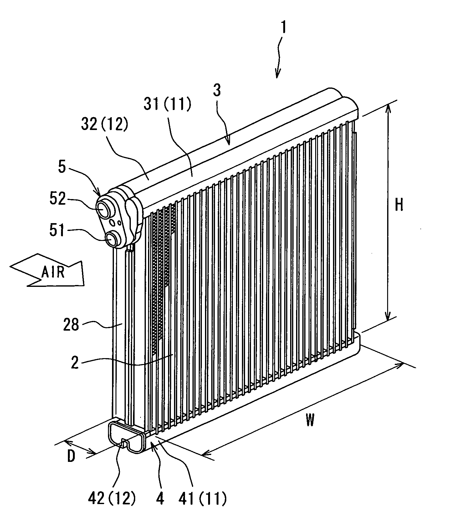
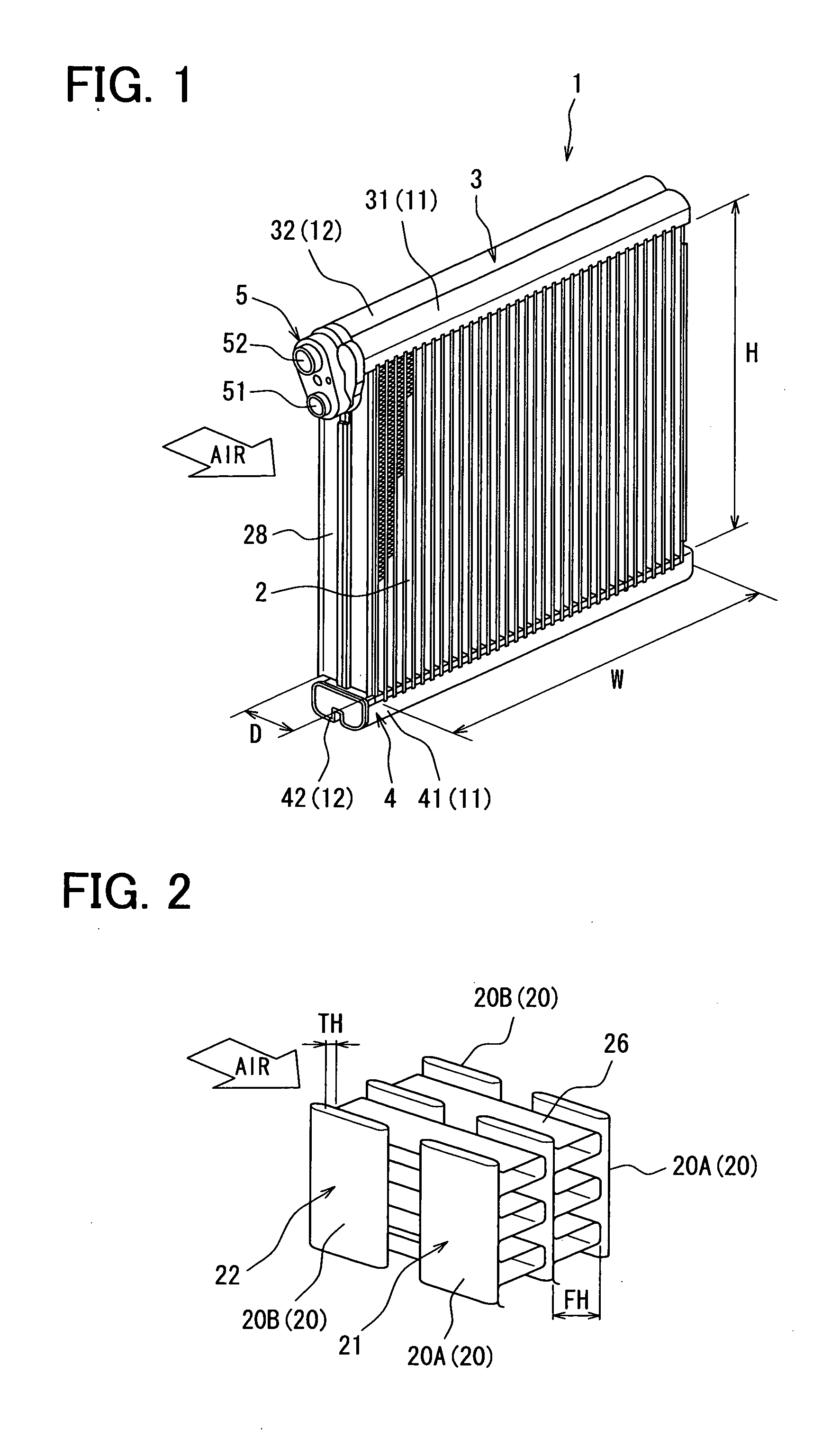
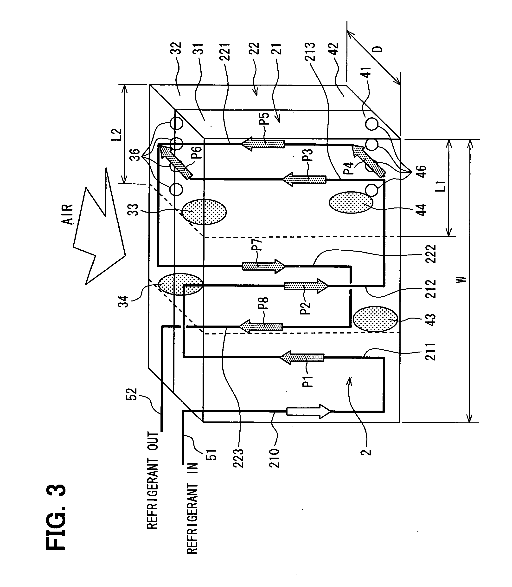
[0024]FIGS. 1 to 3 show an embodiment of the present invention. In the present embodiment, a refrigerant evaporator 1 (hereinafter, simply referred to as the evaporator 1) is, for example, employed to a refrigerant cycle apparatus for a vehicular air conditioner. In the refrigerant cycle apparatus, a refrigerant is compressed into a high temperature, high pressure refrigerant by a refrigerant compressor. The high temperature, high pressure refrigerant is cooled through a radiator, and is decompressed into a low temperature, low pressure refrigerant by a decompressing device. The low temperature, low pressure refrigerant is evaporated in the evaporator 1. In the present embodiment, the refrigerant is, for example, R134a. The radiator serves as a condenser for condensing the refrigerant discharged from the refrigerant compressor.

[0025]The evaporator 1 generally includ...


PUM


Abstract

In a refrigerant evaporator, a core has tubes that are arranged in a core width direction and at least in two rows including a first row and a second row. The first row is disposed downstream of the second row with respect to a flow direction of an external fluid. The tubes of the first row provide a refrigerant upward path and a refrigerant downward path. The core has a thickness equal to or less than 50 mm with respect to the flow direction of the external fluid, and a width equal to or greater than 220 mm with respect to the core width direction. The upward path is further than the downward path with respect to a refrigerant inlet disposed at an end of a first header tank, and has a width equal to or less than 95 mm with respect to the core width direction.

Description

CROSS REFERENCE TO RELATED APPLICATION[0001]This application is based on Japanese Patent Application No. 2007-110889 filed on Apr. 19, 2007, the disclosure of which is incorporated herein by reference.FIELD OF THE INVENTION[0002]The present invention relates to a refrigerant evaporator for evaporating a refrigerant of a refrigerant cycle apparatus.BACKGROUND OF THE INVENTION[0003]A refrigerant evaporator is, for example, described in Japanese Unexamined Patent Application Publication No. 2001-324290 (U.S. Pat. No. 6,339,937). In the described refrigerant evaporator, a core as a heat exchanging part includes a plurality of tubes extending in an up and down direction. The tubes are stacked in a horizontal direction (e.g., a core width direction) and arranged in two rows with respect to a flow direction of air. An upper tank is disposed at upper ends of the tubes of each row, and a lower tank is disposed at lower ends of the tubes of each row. Further, separators are provided in the up...

Claims


Application Information

Patent Timeline
Patent Type & Authority Applications(United States)
IPC IPC(8): F25B39/02
CPCF25B39/02F25B2500/01F28D1/05391F28D2021/0085
Inventor KATOH, YOSHIKI
Owner DENSO CORP
Why Eureka
Try Eureka