
Air conditioning unit for seat

a seat and air conditioning technology, applied in the field of air conditioning units, can solve the problems of limited passage space of the duct, increased pressure loss of the air in the duct, and relatively small space between the cushion member and the back board, and achieve the effect of not increasing the pressure loss of the air passag

Inactive Publication Date: 2007-10-02
DENSO CORP
View PDF24 Cites 34 Cited by
  • Summary
  • Abstract
  • Description
  • Claims
  • Application Information

AI Technical Summary

Benefits of technology

[0006]The present invention is made in view of the foregoing matter, and it is an object to provide an air conditioning unit capable of effectively introducing air to a surface of a seat back of a seat without increasing a pressure loss in an air passage member irrespective of an elastic deformation of the seat back.
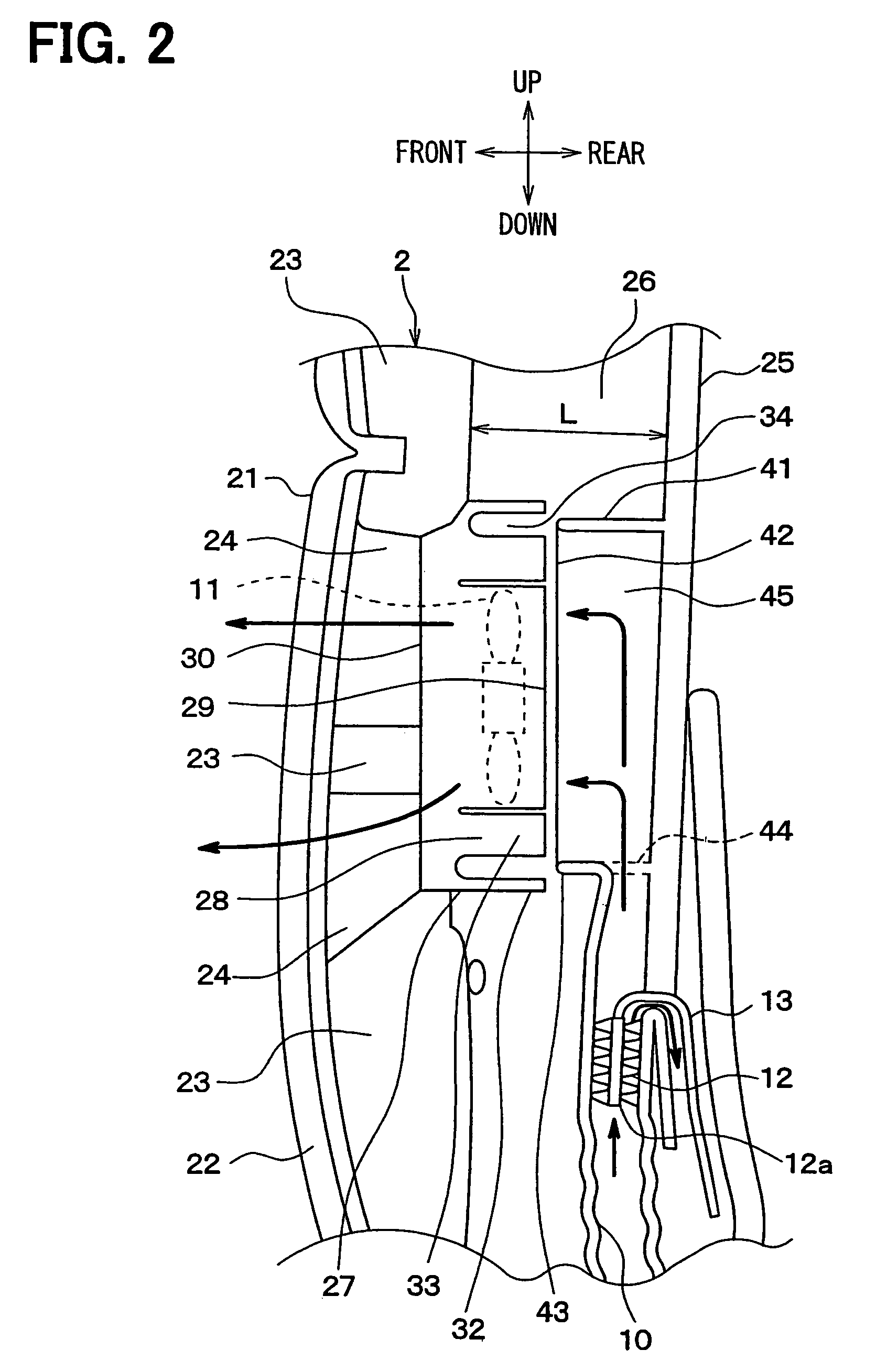
[0009]Namely, even if the cushion member is elastically deformed, an air leakage in the air passage between the second air guide and the first air guide is reduced by the flexible connecting part. Also, it is less likely that an air flow resistance in the air passage between the second air guide and the first air guide will increase. Namely, a pressure loss in the air passage is not increased. Accordingly, a conditioned air is effectively blown to the surface of the seat back from the seat back opening.

Problems solved by technology

However, the space between the cushion member and the back board is relatively small.
As such, a passage space of the duct is limited.
With this, a pressure loss of the air in the duct is likely to increase.
When the duct is deformed or bent with the elastic deformation of the cushion member, the pressure loss in the duct increases.
As a result, it is difficult to sufficiently provide a comfortable air feeling to the person.

Method used


Image

  • Air conditioning unit for seat
  • Air conditioning unit for seat
  • Air conditioning unit for seat

Examples


Embodiment Construction

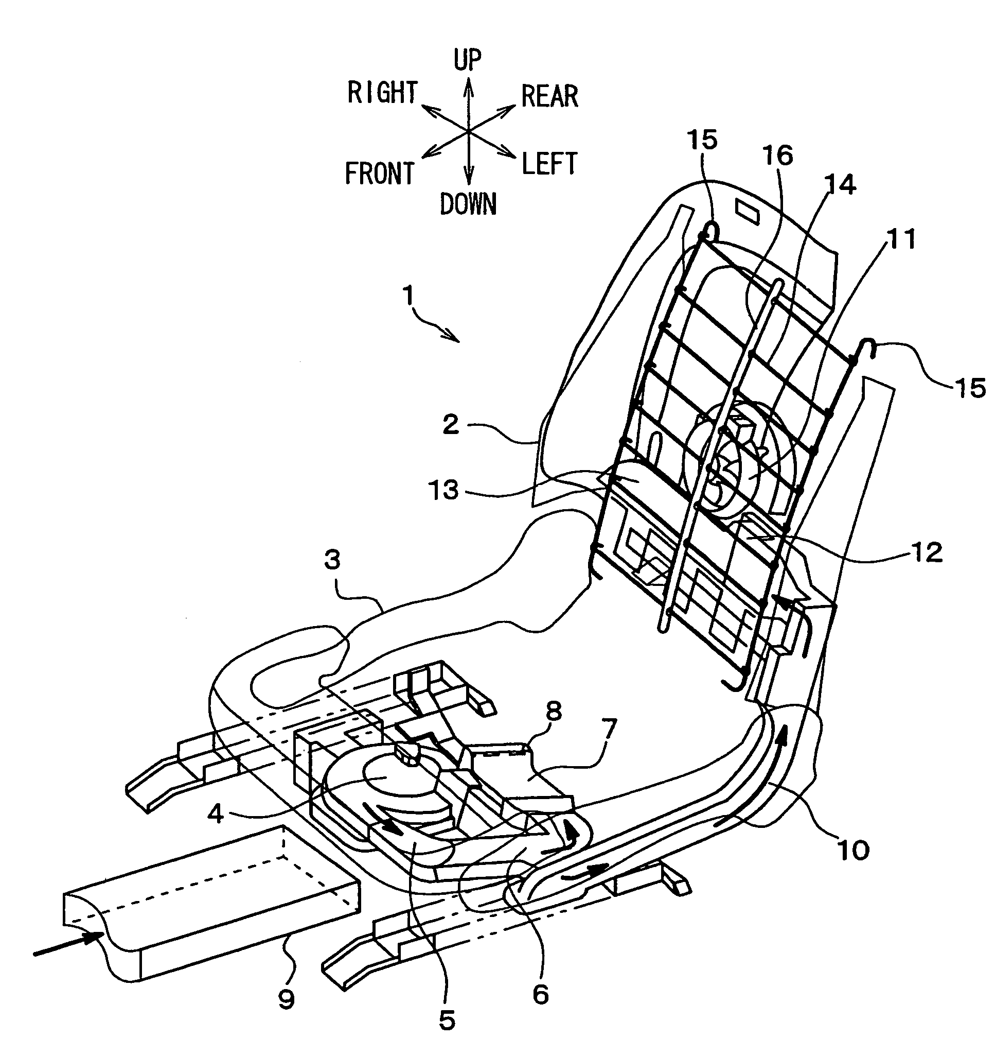
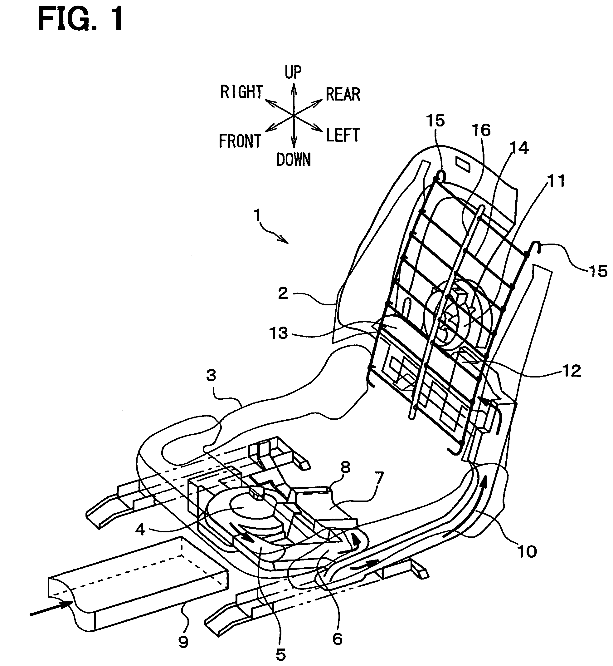
[0017]A first example embodiment of the air conditioning unit for introducing air to a surface of a seat back will now be described with reference to FIGS. 1 to 4. A seat shown in FIG. 1 is a front seat mounted in a passenger compartment of a vehicle, for example. In FIGS. 1 to 4, arrows denote arrangement directions of a seat with respect to the vehicle.

[0018]As shown in FIG. 1, the air conditioning unit is mounted to a seat frame 1 of the seat. The seat has a seat back 2 and a seat cushion 3. The seat back 2 generally receives a load from a back of a passenger sitting on the seat. The seat cushion 3 generally receives a weight of the passenger, in particular a load from a lower half body of the passenger.

[0019]A cushion fan 4 is mounted to a frame of the seat cushion 3 under the seat cushion 3. An air passage member 5 is provided at a discharge portion of the cushion fan 4. The cushion fan 4 sucks air (inside air) existing around or under the seat cushion 3 and blows the air into ...


PUM


Abstract

An air conditioning unit for introducing air to a surface of a seat back has a first air guide, a second air guide and a flexible connecting part. The first air guide is disposed on a rear side of a cushion member of the seat back to follow an elastic deformation of the cushion member. An upstream portion of the first air guide defines an inlet port. A downstream portion of the first air guide communicates with a seat back opening formed in the cushion member. The second air guide is disposed on a back board, which is located on the rear side of the cushion member with a space. The second air guide has an inlet port at an upstream portion thereof and an outlet port at a downstream end thereof. The flexible connecting part flexibly connects the outlet port of the second air guide and the inlet port of the first air guide.

Description

CROSS REFERENCE TO RELATED APPLICATION[0001]This application is based on Japanese Patent Application No. 2005-186269 filed on Jun. 27, 2005, the disclosure of which is incorporated herein by reference.FIELD OF THE INVENTION[0002]The present invention relates to an air conditioning unit for introducing air to a surface of a seat back of a seat.BACKGROUND OF THE INVENTION[0003]A seat air conditioning unit that blows a conditioned air from openings of a seat back toward a hip or back of a person sitting on a seat has been conventionally known. This kind of seat air conditioning unit is for example disclosed in Japanese Patent Publication No. 10-504977 (U.S. Pat. Nos. 5,524,439, 5,626,021, Pat. No. Re. 38,128E). In the seat air conditioning unit disclosed in the above publication, air having passed through a Peltier module is introduced to the openings of the seat back through a duct.[0004]In a seat air conditioning unit, an air ventilation system including such as a blower and a duct f...

Claims


Application Information

Patent Timeline
Patent Type & Authority Patents(United States)
IPC IPC(8): B60N2/56A47C7/74
CPCB60N2/5628B60N2/5657Y10S454/907
Inventor AOKI, SHINJI
Owner DENSO CORP
Learn More