Eureka AIR delivers breakthrough ideas for toughest innovation challenges, trusted by R&D personnel around the world.

Dynamic asymmetric partitioning of program code memory in network connected devices

a network connected device and program code technology, applied in the direction of memory address/allocation/relocation, instruments, television systems, etc., can solve the problems of requiring large amounts of bandwidth, requiring twice the amount of flash memory space to store two separate and complete sets of code, etc., to reduce product returns and service calls, the effect of reducing memory limitations

Inactive Publication Date: 2008-10-23
TEXAS INSTR INC
View PDF6 Cites 199 Cited by
  • Summary
  • Abstract
  • Description
  • Claims
  • Application Information

AI Technical Summary

Benefits of technology

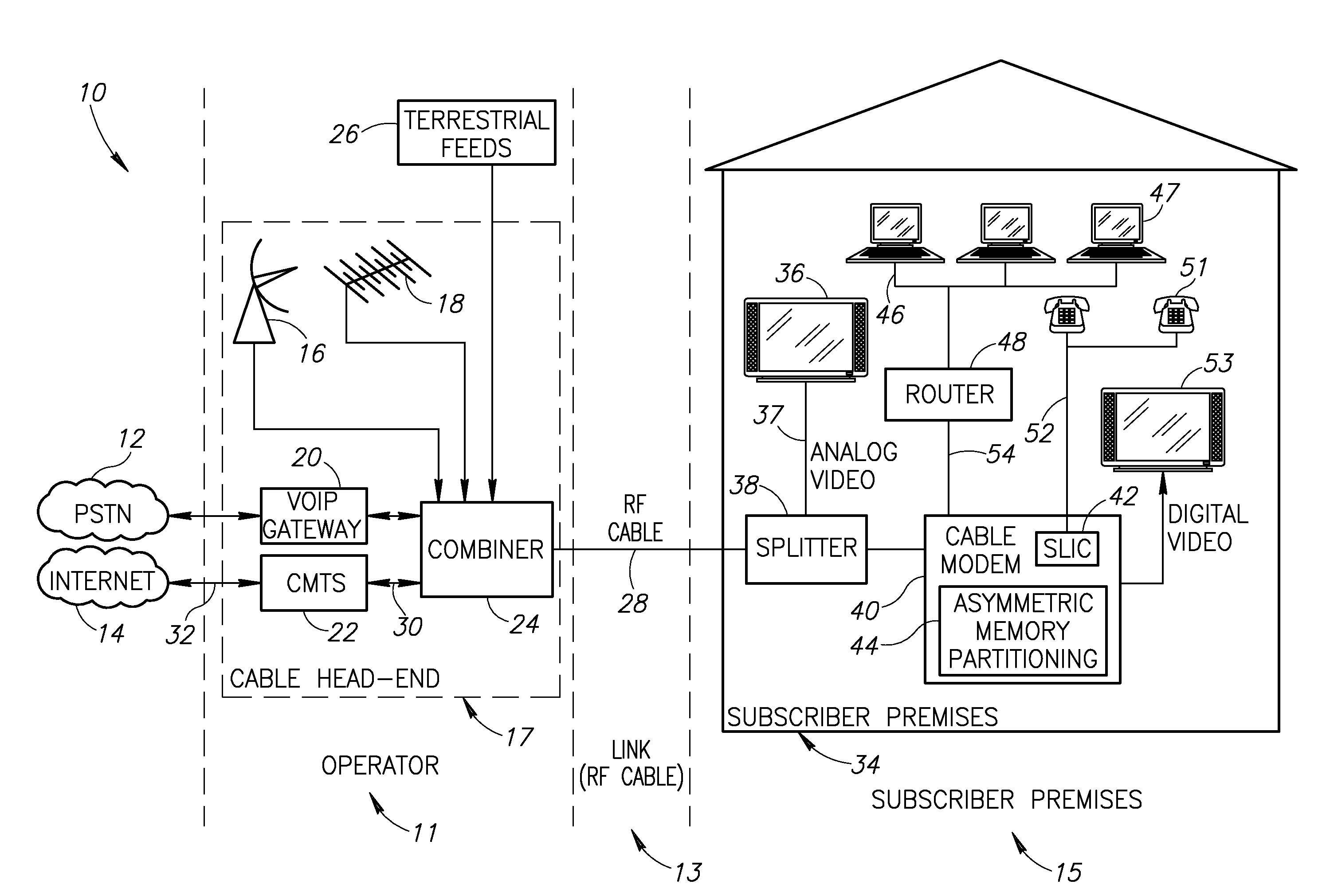
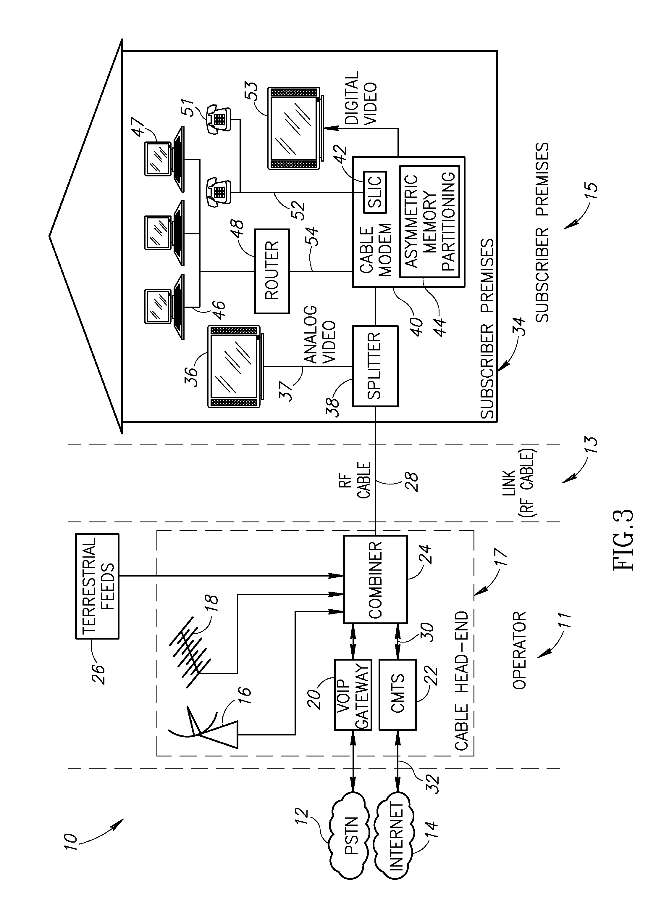
[0029]The present invention is a novel asymmetric memory partitioning mechanism for providing resolving and reducing memory limitations when an increase in software image size is required. The asymmetric memory partitioning mechanism of the present invention is applicable to deployed devices that normally maintain two complete full-functionality software images, simultaneously and independently of each other. The mechanism is especially applicable to previously deployed network connected communication devices that otherwise would be able to accept the increased size of current software image upgrades. An advantage of the fail safe mechanism is that it reduces both product returns and service calls from operators and vendors. One example of the application of the invention is use in a cable modem system adapted to implement the DOCSIS specification.
[0033]Several advantages of the asymmetric memory partitioning mechanism of the present invention include (1) the ability to reduce at least maintain the current cost of devices Bill or Material (BOM) while extending the functionality of the device by enabling the use of smaller non-volatile memory components; (2) the ability to perform upgrades of field deployed devices with software images and applications that support additional functionality, which otherwise could not have been used due to non-volatile memory size limitations of the deployed devices; (3) the ability to perform the upgrade in a seamless remote process that does not require technician intervention or product replacement.

Problems solved by technology

Video and movies, for example, even when compressed using MPEG standards, require large amounts of bandwidth.
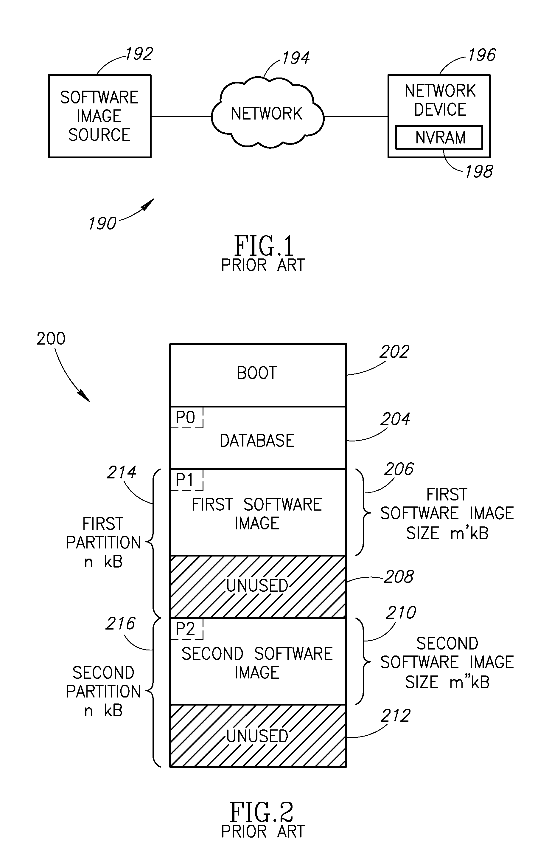
A disadvantage, however, is that twice the amount of flash memory space is required to store two separate and complete sets of code in a compressed format wherein each set comprises both operating and applications code.
The addition of new features and functionality to existing communications products results in an increase in the size of the software image in these devices, which, in turn drives the need for larger and more costly memory devices.
Since the cost of flash memory used in cable modem is significant, the overall cost is increased for a cable modem designed to use a dual banking scheme.
The increase in the size of the software image is problematic when the size of the memory needed grows to a level above the available memory in currently deployed devices.
The problem with previously devices is that the size of their installed memory cannot be changed, resulting in an inability of upgrading field deployed devices.
This structure, however, creates a limitation on the size of the software image which can be programmed into the memory of previously deployed devices.
It also requires the use of larger and more expensive NVRAM components in new devices.
Furthermore, there is a need for a method and system for downloading and updating program code in NVRAM in previously deployed devices that permits an increase in the size of the software image not requiring any physical memory size increases which are costly or impractical.

Method used


Image

  • Dynamic asymmetric partitioning of program code memory in network connected devices
  • Dynamic asymmetric partitioning of program code memory in network connected devices
  • Dynamic asymmetric partitioning of program code memory in network connected devices

Examples


Embodiment Construction

Notation Used Throughout

[0051]The following notation is used throughout this document.

TermDefinitionACAlternating CurrentADCAnalog to Digital ConverterASICApplication Specific Integrated CircuitATMAsynchronous Transfer ModeAVIAudio Video InterfaceBMPWindows BitmapBOMBill of MaterialBWABroadband Wireless AccessCATVCommunity Antenna Television or Cable TVCBWCapture BandwidthCMCable ModemCMTSCable Modem Termination SystemCOCentral OfficeCPUCentral Processing UnitCRCCyclic Redundancy CodeDACDigital to Analog ConverterDCDirect CurrentDECTDigital Enhanced Cordless TelecommunicationsDHCPDynamic Host Control ProtocolDOCSISData Over Cable Service Interface SpecificationDSDownstreamDSLDigital Subscriber LineDSPDigital Signal ProcessorDVRDigital Video RecorderECMEmbedded Cable ModemEDGEEnhanced Data rates for GSM EvolutionEEPROMElectrically Erasable Programmable Read Only MemoryEEROMElectrically Erasable Read Only MemoryEMTAEmbedded Multimedia Terminal AdapterEPROMErasable Programmable Read On...


PUM


Abstract

A novel asymmetric memory partitioning mechanism for providing resolving and reducing memory limitations when an increase in software image size is required. Two partitions are created in non-volatile memory, one smaller than the other. The smaller partition stores a degenerated version of the full-functionality software comprising only essential program code for booting the device and repeating the download and installation procedures until the full-functionality software image is successfully installed in non-volatile memory. The larger portion stores a full-functionality version of the software comprising both essential and non-essential program code. The mechanism also provides the capability of converting devices already deployed in the field. The legacy symmetrical partitioning of the memory in these devices is removed and replaced with asymmetrical partitioning, wherein the smaller partition stores the degenerated software image and the larger partition stores the full-functionality software image.

Description

REFERENCE TO PRIORITY APPLICATION[0001]This application claims priority to U.S. Provisional Application Ser. No. 60 / 912,258, filed Apr. 17, 2007, entitled “Dynamic Asymmetric NVRAM Partitioning of Communication Devices in Remote-Upgradeable Environments”, incorporated herein by reference in its entirety.FIELD OF THE INVENTION[0002]The present invention relates to the field of broadband communication devices and more particularly relates to a dynamic asymmetric partitioning mechanism for partitioning program code memory in network connected devices.BACKGROUND OF THE INVENTION[0003]Currently there are more than 50 million high-speed Internet access customers in North America. Recently, the cable modem has become the broadband connection of choice for many Internet users, being preferred over the nearest rival broadband technology, Digital Subscriber Line (DSL), by a significant margin.[0004]Cable modems are well known in the art. A cable modem is a type of modem that provides access t...

Claims


Application Information

Patent Timeline
Patent Type & Authority Applications(United States)
IPC IPC(8): G06F12/02G06F9/00H04N7/173
CPCG06F8/63
Inventor ZALTSMAN, ETAIGENZEL, ERANLAPID, ADAMSENDEROVITZ, RAN
Owner TEXAS INSTR INC
Why Eureka
Eureka Blog
Learn More