Fluid-operated medical or dental handheld element

a handheld element and flue-operated technology, applied in the field of flue-operated medical or dental handheld elements, can solve the problems of constant fluctuation of the power generated by the generator, constant fluctuation of the light emitted, and the rotational speed of the impeller, so as to reduce friction, and reduce the effect of rotating

Active Publication Date: 2008-10-23
W&H DENTALWERK
View PDF12 Cites 35 Cited by
  • Summary
  • Abstract
  • Description
  • Claims
  • Application Information

AI Technical Summary

Benefits of technology

[0010]The drive of the second impeller with at least a substream of the fluid stream conveyable in the fluid conveying device also yields a considerable advantage in the design of the handheld element, in particular a simplification of the design of the connecting device and the supply system connected to the connecting device, e.g., a supply tube which connects the handheld element to the fluid source. The connecting device may be designed in a known way as a plug connection, a screw connection, a clamp connection or a twist connection, for example, such that regardless of the type of connection, the design and creation of the connecting device should be as simple as possible. This is achieved by driving the second impeller with at least a substream of the fluid stream conveyable in the first fluid conducting device, in which case only one fluid conducting device (e.g., a passageway or a fluid line) need be provided for the drive of the two impellers in the connecting device.
[0025]For axial bearing support of the generator shaft, in one embodiment a spot bearing is used which is arranged downstream from the second impeller. The generator shaft has a rounded or pointed end which has a bearing body with a rounded or pointed surface, e.g., a sphere, a hemisphere, a cone or a truncated cone. Due to the arrangement of the spot bearing downstream from the second impeller, an extremely effective bearing support for the generator shaft is achieved in an advantageous manner without requiring any additional fixation or prestressing of the generator shaft to do so because the fluid stream presses the impeller and the generator shaft connected to it automatically in the direction of the spot bearing. The spot bearing in particular in combination with the friction bearing thus allows a simple, reliable and inexpensive means of providing bearing support for the generator shaft. The spot bearing also results in minimized friction between the generator shaft and the bearing body so the loss of power by the generator is minimized.

Problems solved by technology

One disadvantage of this turbine handpiece is that the rotational speed of the impeller and thus the power generated by the generator fluctuate constantly during operation.
The variable generation and output of power by the generator also lead to constant fluctuations in the light emitted by the light source and in particular lead to extremely weak illumination of the preparation site at low rotational speeds.
When using unsuitable lubricants or after repeated sterilization, there may be changes in the lubricant, in particular changes in viscosity and solidification of the lubricant.
In experiments, the present applicant has found that these changes in the lubricant may in many cases result in complete blockage of the generator, in particular the generator shaft, due to sticking of the bearings which provide the bearing support of the generator shaft.
The blockage of the generator shaft was so tight that even conveyance of fluid through the generator was unable to loosen the blocked shaft, so the entire generator and consequently also the handheld element could no longer be used.

Method used


Image

  • Fluid-operated medical or dental handheld element
  • Fluid-operated medical or dental handheld element
  • Fluid-operated medical or dental handheld element

Examples


Embodiment Construction

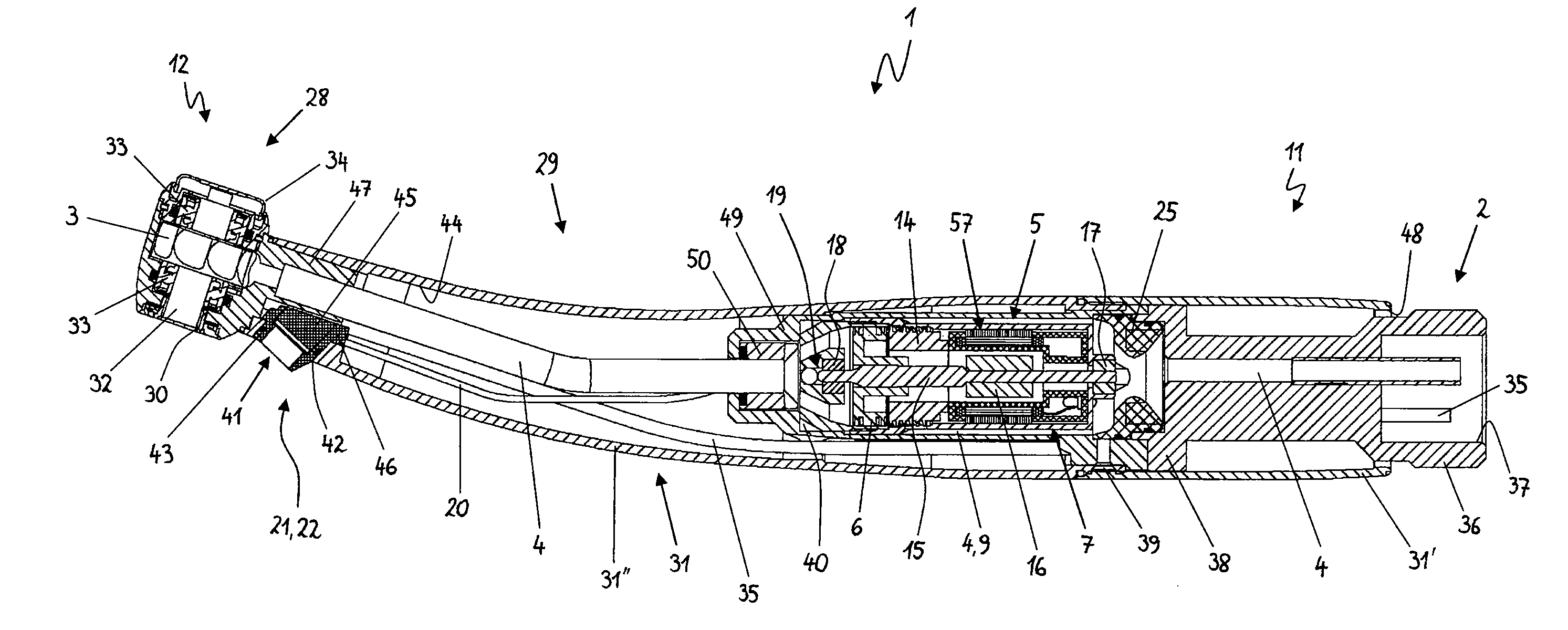
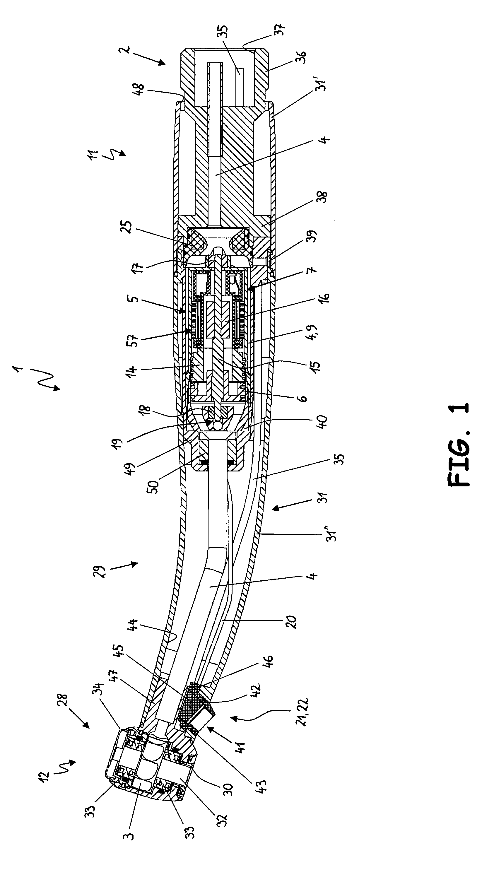
[0037]The medical or dental medical handheld element 1 illustrated in FIG. 1 has a first end 11 and a second end 12. The second end 12 is designed as a head section 28 to which an elongated handle section 29 is detachably connected. The handheld element 1 is designed as a so-called contra-angle handpiece in which the handle section 29 consists of two sections arranged at angles to one another and in which the tool opening 30 is arranged at the side of the head section 28, so that a treatment tool can be inserted into the head section 28 transversely the handle section 29. An outer sleeve 31 in one or more parts surrounds the handle section 29 and the head section 28. The handheld element may of course also have other outer shapes, in particular a straight shape or a pistol shape.

[0038]In the front area or head section 28 of the handle element 1 there is a tool receptacle 32 that is accessible through the tool opening 30 in a known manner. The tool receptacle 32 is accommodated at le...


PUM


Abstract

A fluid-operated medical or dental handheld element is disclosed, having a connecting device for connecting the handheld element to a fluid source so that a first impeller can be induced to rotate by a fluid stream to cause a tool to execute a driving motion, a fluid conducting device arranged between the connecting device and the first impeller for conveying a fluid stream away from or toward the first impeller, and a generator for generating electric power. The generator includes a second rotatable impeller that can be driven by at least a substream of the fluid stream conveyable in the first fluid conducting device. One result is more constant generation and output of power by the generator independent of the rotational speed of the first impeller, thereby insuring a more constant power supply to a power consuming device connected to the generator.

Description

CROSS REFERENCE TO RELATED APPLICATION[0001]The present application claims priority from pending European Patent Application No. 07008056.9, filed Apr. 20, 2007, and European Patent Application No. 08007019.6, filed Apr. 9, 2008, both of which are incorporated herein by reference.BACKGROUND[0002]1. Field[0003]This application relates to a fluid-operated medical or dental handheld element with a generator for generating electric power.[0004]2. Description of Prior Art[0005]U.S. Pat. No. 5,800,172 discloses a turbine handpiece in which the impeller, which is operated by compressed air and induces rotation of the tool, is also used as part of an electromechanical transformer which generates electric current for a light source provided in the head of the handpiece.[0006]One disadvantage of this turbine handpiece is that the rotational speed of the impeller and thus the power generated by the generator fluctuate constantly during operation. Such fluctuations are induced by different load...

Claims


Application Information

Patent Timeline
IPC IPC(8): A61C1/05A61C1/06
CPCA61C1/05
Inventor RAUCHENZAUNER, STEPHANSCHMIEDLECHNER, KARL
Owner W&H DENTALWERK
Why Eureka
Try Eureka