
Actuating drive

a technology of actuating drive and drive shaft, which is applied in the direction of computer control, program control, instruments, etc., can solve the problems of potentiometers being generally subject to wear, measurement accuracy can be inadequate, and the complexity of the hardware for carrying out the method can be quite high

Inactive Publication Date: 2008-10-23
ABB (SCHWEIZ) AG
View PDF14 Cites 14 Cited by
  • Summary
  • Abstract
  • Description
  • Claims
  • Application Information

AI Technical Summary

Benefits of technology

[0018]According to a further exemplary feature, the pattern support can be illuminated by an intermittent light source. In consequence, the position detection device can use less energy than if the pattern support were to be illuminated continuously. Furthermore, this operating mode is similar to discontinuous operation of sequentially operated optical scanning devices and downstream processing means.
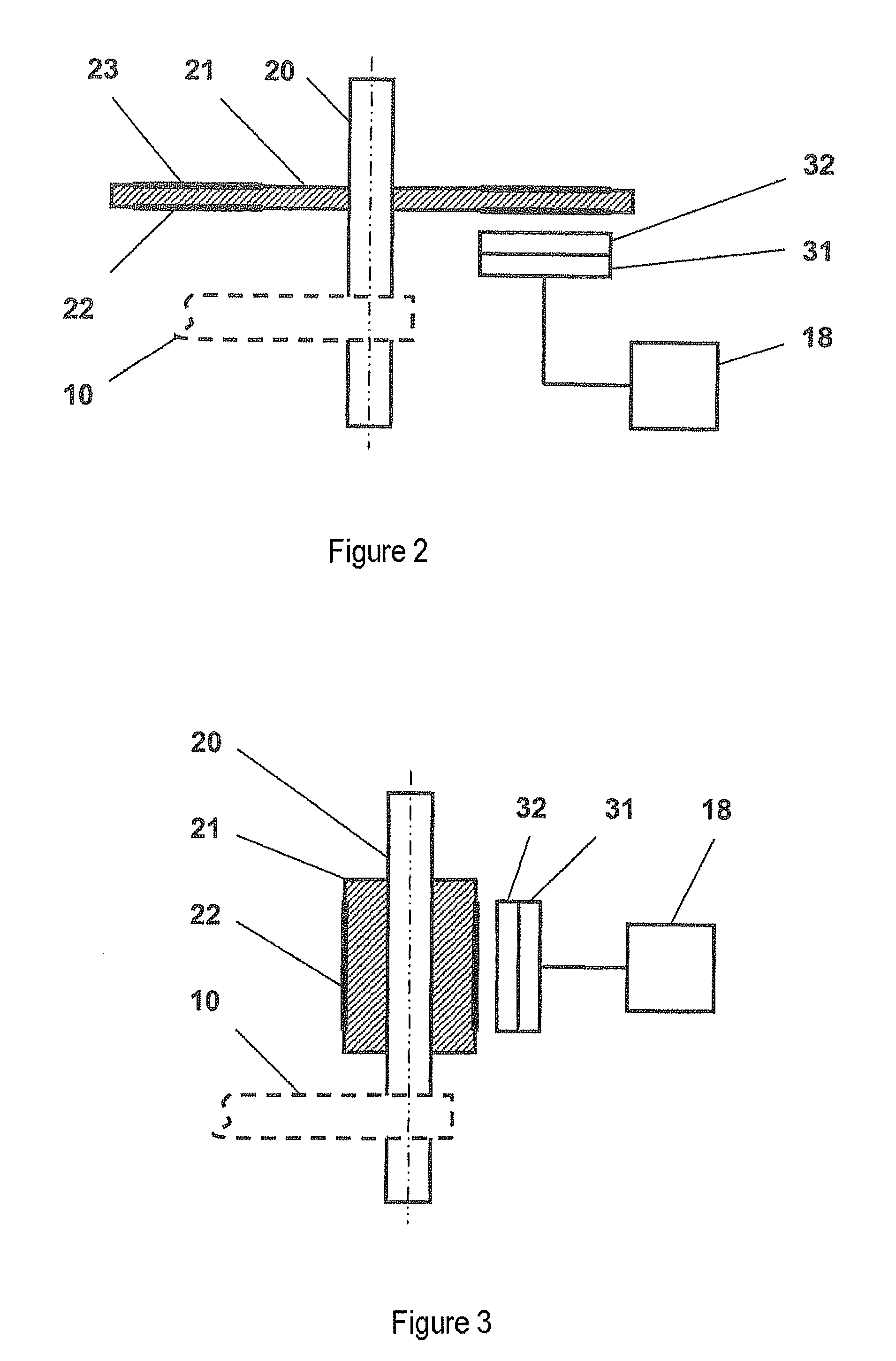
[0019]Further exemplary features of the disclosure provide for the pattern to be in the form of a circumferential track, which has an annular shape or a shape in the form of a tire, dependent on the geometric shape of the pattern support. Even if the circumferential track is scanned only partially for position detection during correct use, over a segment which corresponds to the movement of the actuating element, then the completely circumferential track on the pattern support can have an advantage that the pattern support can initially be mounted in any desired angular position with respect to the scanning device, and the initial and final values of the scanning range can be determined just once during an initialization process on commissioning. This can avoid human errors in adjustment.
[0020]Further exemplary features provide for the pattern to be in the form of concentrically circumferential, annular tracks that are coincident on both disk faces of the pattern support, which is in the form of a disk. Irrespective of the installation orientation, in an exemplary embodiment, one of the tracks can be always at the focus of the scanning device, and the instantaneous position of the actuating element can thus be detected. A pattern support in this form can be advantageously insensitive to incorrect installation.

Problems solved by technology

Although this method allows non-contacting position measurement, the hardware complexity for carrying out the method can be quite high, however, and the measurement accuracy can be inadequate, in particular in the event of vibration in rough installation operation.
For example, potentiometers are generally subject to wear, particularly when they are used in an area in which severe mechanical vibration or shaking occurs.
This wear is evident by increasing wear at the operating point of the potentiometer.
The use of rotary capacitors can be very expensive, since complex protective measures can be instituted in this case against moisture and, furthermore, very precise mechanical bearings are used.
The use of differential transformers can be disadvantageous because of the expensive mechanical bearing, since lateral movements of the magnet in the coil are suppressed.
The electronics which are required in a corresponding manner for supply are also too expensive and have a relatively high power consumption.

Method used


Image

  • Actuating drive
  • Actuating drive
  • Actuating drive

Examples


Embodiment Construction

[0012]An actuating drive as disclosed herein can include means for detection of the position of an actuating element, which means can have a high measurement accuracy while drawing little current, and are insensitive to vibration.

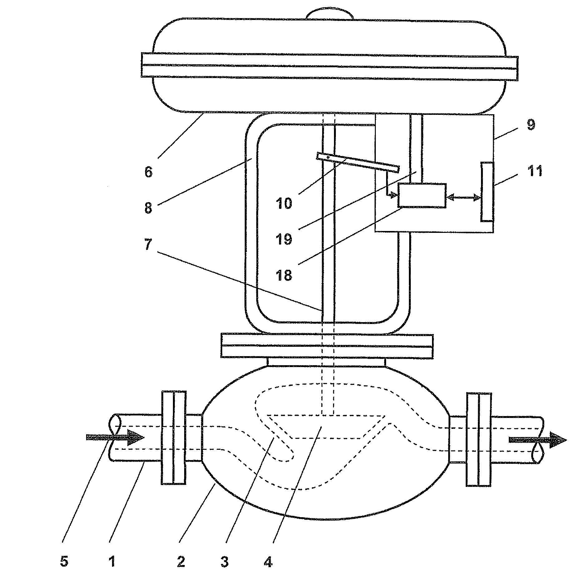
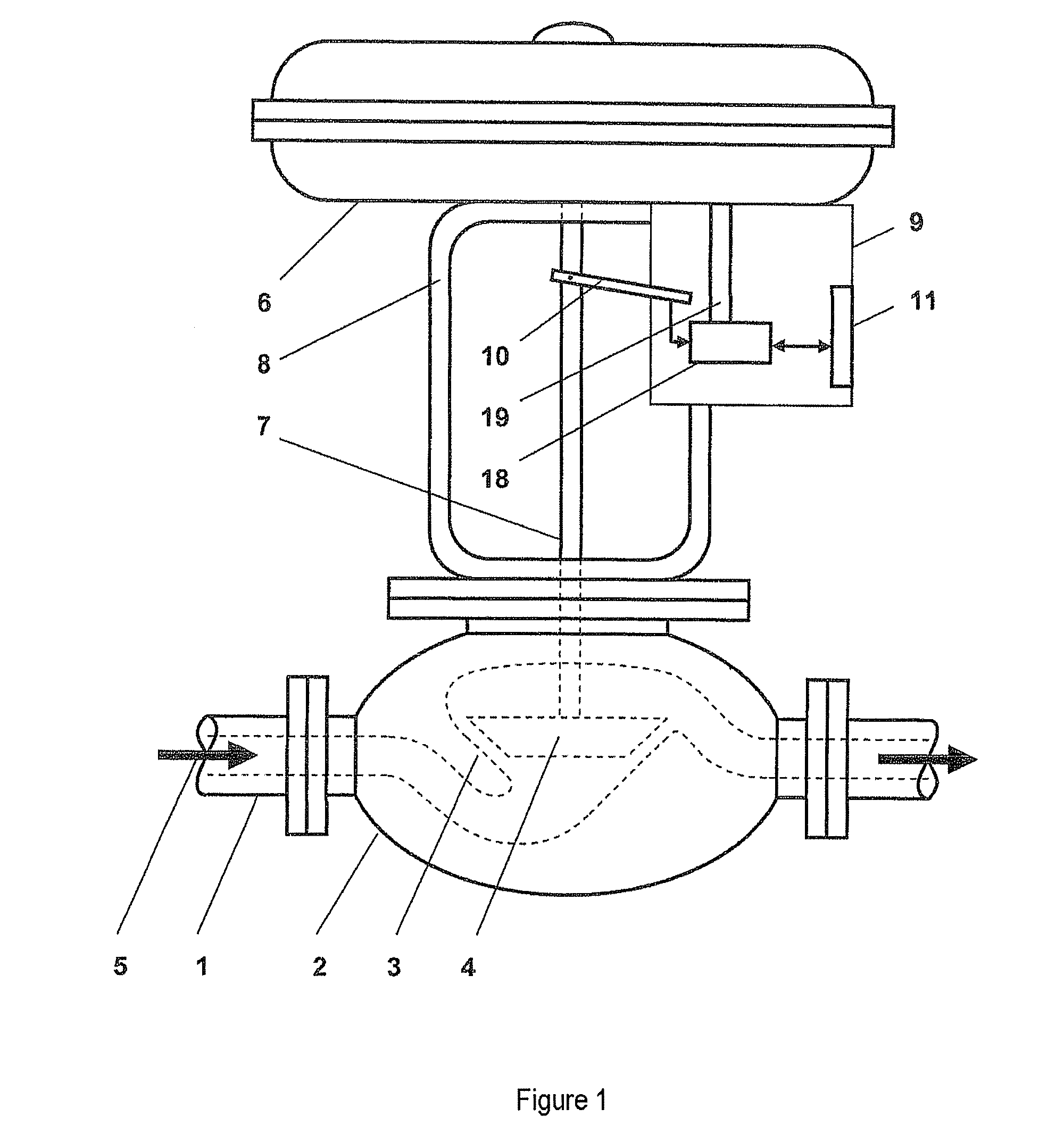
[0013]An exemplary actuating drive for control of an actuating element can include a position detection device configured for detection of the actual position of the actuating element and a regulator unit configured for operational connection with the position detection device for comparison of an actual position with a predeterminable set position and for production of an actuating signal for driving the actuating drive.

[0014]In an exemplary embodiment, the position detection device which is associated with the actuating drive has a pattern support, at least part of whose surface is covered by a pattern which can be scanned optically. Furthermore, a stationary optical scanning device can be provided, whose optical axis is aligned with the pattern.

[0015]The...


PUM


Abstract

The disclosure relates to an actuating drive for control of an actuating element for automation in process installations. An exemplary actuating device drive for control of an actuating element comprising: a position detection device configured for detection of an actual position of the actuating element; a regulator unit configured for operational connection with the position detection device for comparison of an actual position with a predeterminable set position and for production of an actuating signal for driving the actuating drive, wherein the position detection device has a pattern support, at least part of whose surface is covered by a pattern which can be scanned optically; and a stationary optical scanning device, whose optical axis is aligned with the pattern.

Description

RELATED APPLICATION[0001]This application claims priority under 35 U.S.C. §119 to German Patent Application No. 10 2007 019 045.1 filed in Germany on Apr. 23, 2007, the entire content of which is hereby incorporated by reference in its entirety.TECHNICAL FIELD[0002]An actuating drive for control of actuating elements for automation in process installations is disclosed.BACKGROUND INFORMATION[0003]Known actuating drives are equipped with a control device which compares the instantaneous actual position of the actuating element with a predetermined set position, and drives the actuating drive such that the actual position is changed, for compensation purposes, in the direction of the predetermined set position. For this purpose, the actuating drive has a position sensor arrangement, which signals the instantaneous actual position of the actuating element to the control device.[0004]DE 42 39 635 A1 discloses a method for detecting the position of the valve rod movement for electropneum...

Claims


Application Information

Patent Timeline
IPC IPC(8): F16K37/00G05B19/29G01B11/14
CPCF16K31/126F16K37/0058G01D5/3473Y10T137/8242
Inventor SCHOLZ, WOLFGANGMARKS, FRANK
Owner ABB (SCHWEIZ) AG
Learn More