
Low-mass-trigger controlled release of projectiles having variable energies and numbers in a centrifugal propulsion weapon, and methods of weapon use

a centrifugal propulsion and variable energy technology, applied in the direction of weapons, launching weapons, white arms/cold weapons, etc., can solve the problems of limited projectile speed, inability to feed the desired amount of projectiles in any centrifugal operated weapon, and the power required to rotate the radial barrel is too great to develop an economically feasible rapid fire weapon, etc., to achieve the effect of high ra

Inactive Publication Date: 2008-10-23
ST GEORGE CHARLES
View PDF12 Cites 4 Cited by
  • Summary
  • Abstract
  • Description
  • Claims
  • Application Information

AI Technical Summary

Benefits of technology

[0027]It is an object of the present invention, as it was of both the Inventor's previously patented invention and his invention of the related patent application, to provide a novel automatic weapon utilizing centrifugal force which provides both a high rate of discharge (rounds per minute) and high muzzle velocity.
[0028]It likewise remains an object to provide such an automatic weapon which operates in a continuous stealth mode to increase its operational capabilities and the survivability of the weapon crew.
[0029]It likewise remains a further object to provide such a weapon which effectively eliminates overheating, jamming, the need for synchronized feeding and peripheral discharge, and any requirement for mechanical compensation for possible gyroscopic reaction.

Problems solved by technology

A limitation of such a construction is that the power required to rotate the radial barrel is too great to develop an economically feasible rapid fire weapon.
Such construction has, however, limited the speed of the projectiles for various reasons including (1) rotation of the bullet in a direction reverse to travel direction of the projectile and (2) the provision of a peripheral barrier which prevents emission of the projectile at the precise moment that it achieves its maximum speed at the exit end of the barrel.
Associated with the foregoing type of gun has been the problem of overcoming the strong gyroscopic reaction force of a rotating impeller that resists turning and moving a gun when aiming in a plane that is not perpendicular to the axis of rotation of the impeller.
Such gravity feed loading systems are not able to feed the desired amount of projectiles in any centrifugal operated weapon at high speeds since the rotating member that provides the centrifugal force to propel the projectiles expels the projectiles much faster than any gravity feed loading system can supply.
Thus, the rate of fire of these weapons is restricted by having the rate of fire controlled by gravity-fed loading systems.
Moreover, it imparts negliable vibration to the centrifugal gun at all operational speeds.
It is thus hard to believe the obvious destructive power of the ejected projectiles, which can be fully individually as energetic as bullets from high power ammunition rounds, and at considerably rates of fire.

Method used


Image

  • Low-mass-trigger controlled release of projectiles having variable energies and numbers in a centrifugal propulsion weapon, and methods of weapon use
  • Low-mass-trigger controlled release of projectiles having variable energies and numbers in a centrifugal propulsion weapon, and methods of weapon use
  • Low-mass-trigger controlled release of projectiles having variable energies and numbers in a centrifugal propulsion weapon, and methods of weapon use

Examples


first embodiment

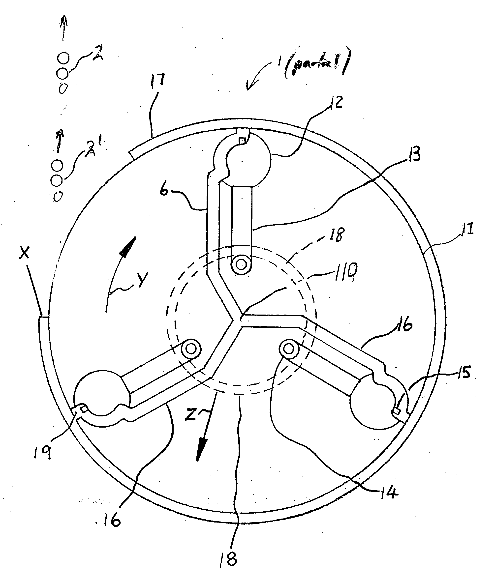
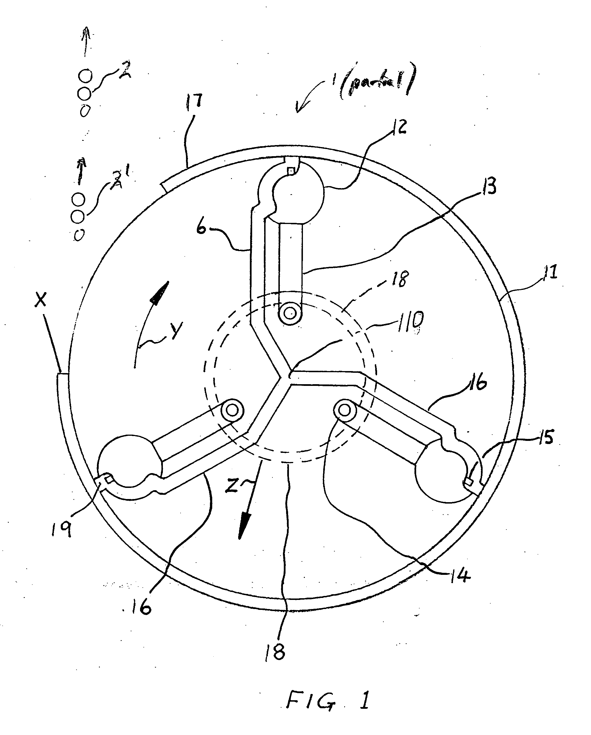
[0083]FIG. 1 is top plan view of a centrifugal having a first embodiment projectile release mechanism in accordance with the related predecessor invention in use for ejecting projectiles, by way of illustration in burst of six projectiles each burst.

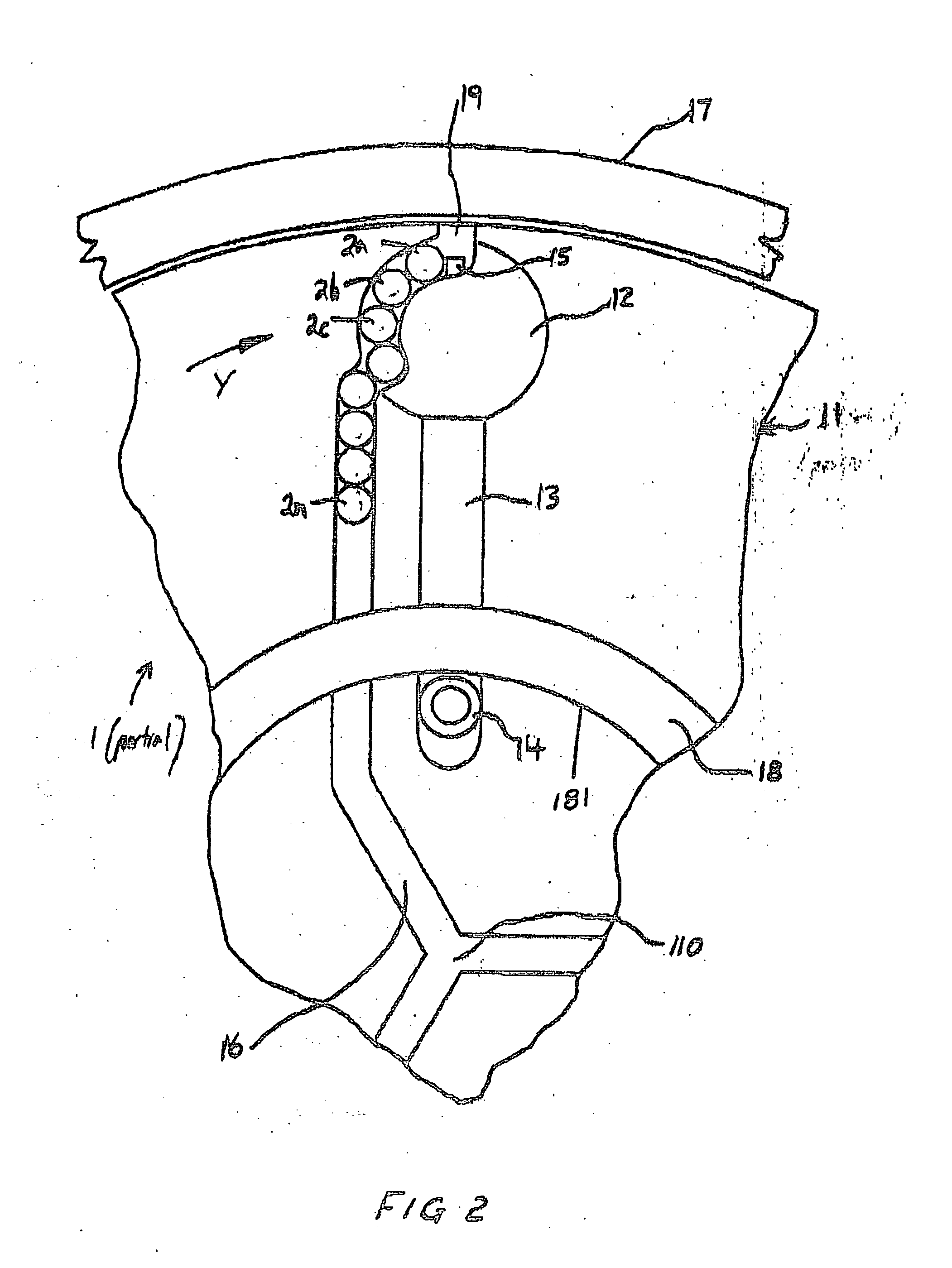
[0084]FIG. 2 is a detail top plan view at expanded scale of the first embodiment projectile release mechanism in accordance with the related predecessor invention at a first time and in a first, projectile-ejection-obstructing, position.

[0085]FIG. 3 is a detail top plan view at expanded scale of the first embodiment projectile release mechanism in accordance with the related predecessor invention at a second time and in a second, projectile-ejection-enabling, position.

[0086]FIG. 4 is a detail top plan view at expanded scale of the first embodiment projectile release mechanism in accordance with the related predecessor invention at a third time and in a third, projectile-ejection-obstructing, position with a previously gated projectile st...

second embodiment

[0092]FIG. 10 is a side view of a centrifugal gun having an improved, second embodiment, projectile release trigger mechanism in accordance with the present invention.

[0093]FIG. 11 is a view of an exemplary three arm selectors which, in their movement relative to a case, are a substantial part of the realization of the improved second embodiment of the projectile release mechanism in accordance with the present invention previously seen in part in FIG. 11.

[0094]FIGS. 12 and 13 show the detail movement of an arm within the previous, first embodiment, projectile release trigger mechanism for a centrifugal gun, previously seen in FIGS. 1-7, in accordance with the related predecessor inventions.

[0095]FIGS. 14 and 15 show movement of a selector, replacing the arm of FIGS. 12 and 13, within the improved, second embodiment, projectile release trigger mechanism for a centrifugal gun in accordance with the present invention

[0096]FIG. 16 shows a handle bar assembly within the improved, second...

third embodiment

[0099]FIG. 19, consisting of FIGS. 19a and 19b, are respective top and side plan views of a centrifugal gun having an improved, third embodiment, projectile release trigger mechanism in accordance with the present invention in a first, projectile-release-obstructing, position.

[0100]FIG. 20, consisting of FIGS. 20a and 20b, are respective top and side plan views of a centrifugal gun with the improved, third embodiment, projectile release trigger mechanism in accordance with the present invention previously seen in FIG. 19, this third embodiment of the release mechanism now in a second, projectile-releasing, position.


PUM


Abstract

A weapon 1 peripherally discharging projectiles 2a-2n, normally ball bearings, at sustained high rates under centrifugal force preferably has two opposed members 11 each rotating within a housing, or guide track, 10. Each rotating member 11 preferably has at least two channels, or track, 16 with a radial component within which projectiles 2a-2n received near the center of rotation progress radially outwards until first escaping at 19, and then being ejected at X, under centrifugal force at the periphery of the at least one rotating member 11. A projectile release mechanism controls the timing, locations, and numbers of projectiles released per rotation of the at least one rotating member. This mechanism uses (1) opposed connected elongate members 13, substantially positioned along a radius line and within the at least one member 11 with its distal end protruding within the at least one channel 16 and with a proximal end cam follower 13 contacting the interior circumference 181 of (2) a ring cam 18, non-rotating to the housing 10 and movable between positions both coaxial, and displaced, to the rotational axis of the at least one rotating member 11. The elongate members 13 move (1) radially outward under centrifugal force of the rotation of the at least one rotating member 11 until its distal end protrudes within the at least one channel 16, therein obstructing passage of projectiles 2a-2n along the channel 16 and any ejection of these projectiles 2a-2n from the periphery of the at least one rotating member 11, until (2) the cam follower 14 of the elongate arm 13 contacts during rotation the cam 181 surface of the ring cam 18, pulling the elongate member 13 against centrifugal force radially inwards until its distal end ceases to protrude within the channel 16, losing passage of projectiles 2a-2n along the channel 16 for subsequent escape at 19 and for ejection at X.

Description

REFERENCE TO A RELATED APPLICATION[0001]The present application is a continuation-in-part of U.S. patent application Ser. No. 11 / 283,445 filed Nov. 17,2005, for TRIGGER CONTROLLED RELEASE OF CONTROLLED NUMBERS OF PROJECTILES AT EACH OF CONTROLLED NUMBER OF INSTANCES PER REVOLUTION to the selfsame inventor as is the present application.[0002]The predecessor application claims benefit of priority of Australian Provisional Patent Application No. 2004906627, filed Nov. 19, 2004, for a WEAPON USING CENTRIFUGAL PROPULSION FOR PROJECTILES also to the selfsame inventor as is the present patent applicationBACKGROUND OF THE INVENTION[0003]1. Field of the Invention[0004]The present and related inventions generally relate to automatic weapons using centrifugal force to propel projectiles, and methods of using such weapons.[0005]The present invention particularly relates to (1) an improved projectile trigger and release mechanisms for rotating weapons propelling projectiles by centrifugal force,...

Claims


Application Information

Patent Timeline
IPC IPC(8): F41B3/04
CPCF41B3/04
Inventor ST. GEORGE, CHARLES
Owner ST GEORGE CHARLES
Learn More