Load-sensor-equipped vehicle operating pedal device and load-sensor-equipped operating device

a technology of operating pedal and load sensor, which is applied in the direction of mechanical control devices, instruments, force/torque/work measurement apparatus, etc., can solve the problems of increasing the size of the device as a whole, the device becomes complicated in its structure, and the usual pushrod cannot be used intact, so as to reduce the amount of deformation (strain value), reduce the flexure deformation of the case member, and increase the detection precision of the operating force

Active Publication Date: 2008-10-16
TOYODA IRON WORKS CO LTD
View PDF18 Cites 15 Cited by
  • Summary
  • Abstract
  • Description
  • Claims
  • Application Information

AI Technical Summary

Benefits of technology

[0049]The case member is postionally mounted in the sensor-mounting member with the plural mounting portions held in engagement with the plural load receiving portions formed in the sensor-mounting member, respectively, in a fixed posture. In addition, even if the direction of the input load F, transmitted from the shaft-like member to the case member through the strain body, is relatively varied due to a relatively pivotal movement of the pivotably connecting section in accordance with depression of the operating pedal, the plural load receiving portions always bear the input load F via the plural mounting portions. This minimizes flexure deformation of the case member occurring due to stress concentration.
[0050]This prevents the strain body from encountering undesirable deformation or a reduction in deformation amount (strain value) resulting from the flexure deformation of the case member, thereby providing increased detecting precision of the operating force. In addition, the device can be formed in a structure with lighter weight and lower cost than those accomplished with the other device employing high-strength material with the lessened occurrence of flexure deformation, or adopting a case member of a large size.
[0051]Even if the direction of the input load F varies due to relatively pivotal movement of the pivotably connecting section in accordance with depression of the operating pedal, the input load F can be always born with the plural load receiving portions via the plural mounting portions. Thus, the load sensor can be maintained in a fixed position and posture, so that there is no fear of degraded detecting precision of the operating force that would occur in the cylindrical case member due to the swaying displacement thereof. Moreover, the case member has minimized flexure deformation. Thus, even if the input load F varies in the direction, a deforming position of the strain body is merely caused to vary with no occurrence of a complicated deforming pattern, thereby suppressing a variation in deformation amount. As a result, the strain body has a strain value maintained at an approximately fixed level regardless of the directional variation of the input load F with the input load F kept in a fixed amount. This allows the load sensor to have increased reliability with stabilized detecting precision during the actual pedal operation with the input load F progressively increasing.
[0052]The case member of the load sensor sufficiently has the plural mounting portions and the plural load receiving portions that are held in engagement with each other. This results in improved assembling possibility of the load sensor. In addition, when assembling the load sensor to the sensor-mounting member, the other area of the sensor-mounting member than the mounting portions and the load receiving portions necessarily has no need to be formed in high dimensional precision. This alleviates required shape precision of the parts, enabling a reduction in production cost.
[0053]With the second aspect of the present invention, the load sensor includes the case member having the pair of flat mounting surfaces, convexly formed at the predetermined apex angle α on the plane perpendicular to the axis of the shaft-like member, which are brought into surface contact with the plurality of flat rest surfaces of the sensor-mounting member, respectively. With such a structure, the load sensor can be positioned in a fixed posture. In addition, even if the direction of the input load F transmitted from the shaft-like member to the case member through the strain body, is relatively varied due to relatively pivotal movement of the pivotably connecting section in accordance with depression of the operating pedal, the input load F can be always born with the pair of rest surfaces through the pair of mounting surfaces. This minimizes the occurrence of deformation of the case member caused by stress concentration. As a result, this prevents undesirable deformation of the strain body caused by deformation of the case member, or a reduction in a deformation amount (strain value), providing improved detecting precision of the operating force. Moreover, the device can be formed with a lighter weight and lower cost than those achieved with a case employing high-strength material with lessened flexure deformation or another case adopting a case member of a large size.
[0054]With the third aspect of the present invention, a concrete condition is regulated for the input load F to be always born with the pair of rest surfaces through the pair of mounting surfaces even when the direction of the input load F is varied due to relatively pivotal movement of the pivotably connecting section in accordance with depression of the operating pedal. Such a condition is regulated in terms of the orientations and the apex angle α of the rest surfaces.

Problems solved by technology

With such a device disclosed in Patent Publication 1, however, since the pushrod needs to be formed with an elongate hole for connection to the connecting pin to allow the pushrod to move relative to the connecting pin axially, no usual pushrod can be used intact.
As a result, the device becomes complicated in structure.
This results in an increase in size of the device as a whole, causing an increase in production cost.
Due to flexure deformation caused in the case member 208, the strain body 206 encounters undesirable deformation like bending, torsion or the like, and in alternative, the strain body 206 has a lessened deformation amount, resulting in a possibility of degraded detecting precision of the operating force.
In view of this, there is a fear of occurrence of degraded detecting precision of the operating force.
With the operating pedal device 200 used in actual practice, since the input load F increases depending on a depressing stroke of the operating pedal 16, there is a fear of a difficulty occurred in correctly detecting the increased input load F, i.e., the operating force.

Method used


Image

  • Load-sensor-equipped vehicle operating pedal device and load-sensor-equipped operating device
  • Load-sensor-equipped vehicle operating pedal device and load-sensor-equipped operating device
  • Load-sensor-equipped vehicle operating pedal device and load-sensor-equipped operating device

Examples


embodiment 1

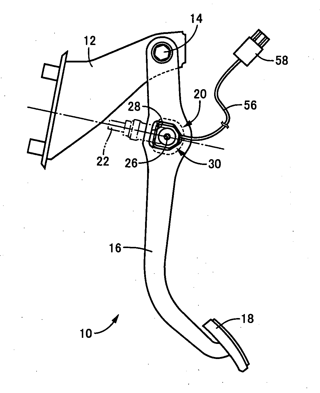
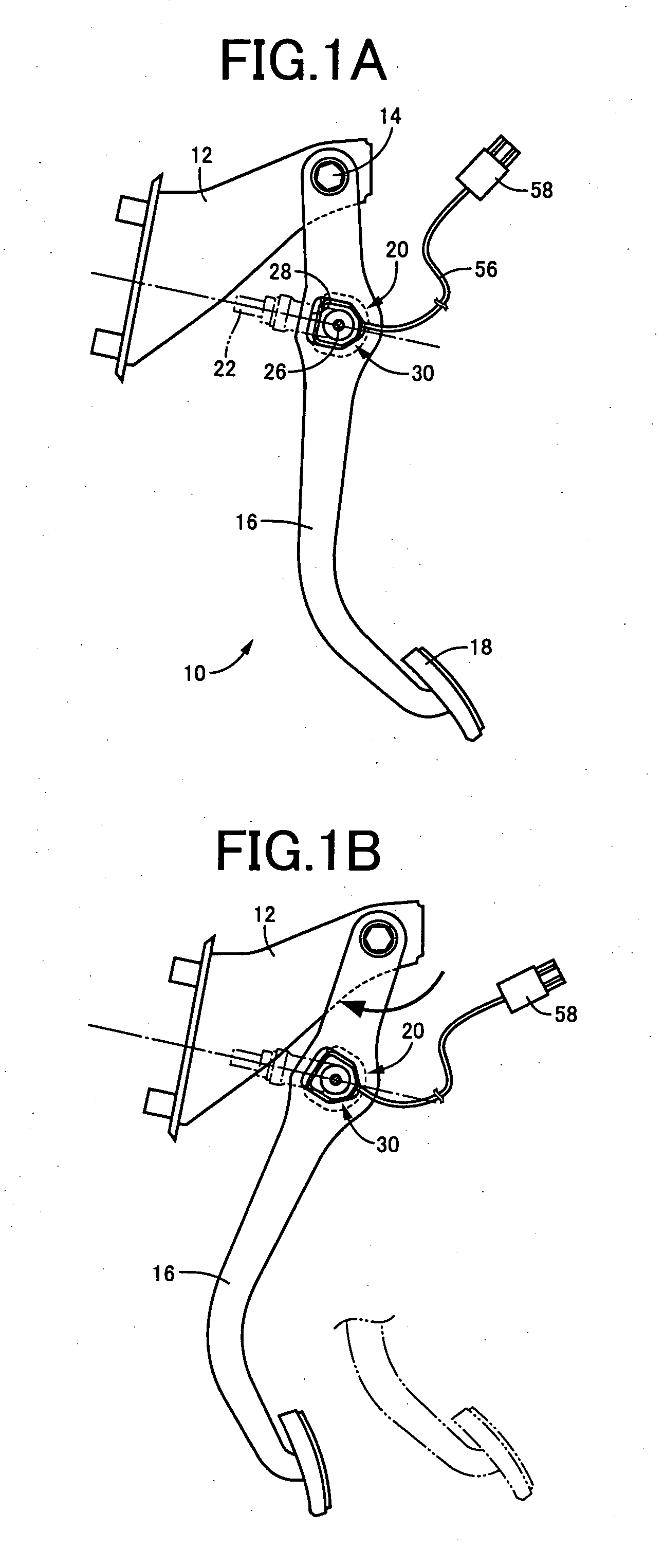
[0119]FIGS. 1A and the 1B are views showing an operating pedal device 10 of one embodiment according to the present invention for a service vehicle brake. FIG. 1A shows an operating pedal 16 in a state depressed to an intermediate point of a depressing stroke, and FIG. 1B shows another state of the operating pedal 16 that is further depressed to a terminal end of the depressing stroke. The vehicle operating pedal device 10 represents a case in which the present invention is applied to the operating pedal device 200 shown in FIGS. 21A and the 21B. The operating pedal 16 is formed a sensor-mounting hole 28 for mounting a load sensor 30 therein.

[0120]Like the load sensor 204 described above, the load sensor 30 has the wire harness 56 having a distal end coupled to a connector 58, through which the wire harness 56 is connected to a control circuit section of a vehicle. The operating pedal device 10 corresponds to a claimed operating device, and the operating pedal 16 corresponds to a cl...

embodiment 2

[0164]FIGS. 9A and the 9B are views corresponding to FIGS. 1A and 1B. FIG. 9A shows a state with a depressing stroke placed at an intermediate point thereof, and FIG. 9B shows another state with the depressing stroke placed at a final stage thereof. A vehicle operating pedal device 80 includes an intermediate lever 82, through which the operating force is transmitted from the operating pedal 16 to the operating rod 22.

[0165]The intermediate lever 82 has one longitudinal end pivotably mounted on the pedal support 12 by means of a support pin 84 extending parallel to the support shaft 14, and a longitudinally intermediate portion pivotably connected to the operating pedal 16 via a connecting link 86. This allows the intermediate lever 82 to be pivoted about the support pin 84 mechanically in conjunction with depression of the operating pedal 16. The connecting link 86, has both longitudinal ends pivotably relatively connected to the operating pedal 16, and the intermediate lever 82 vi...

embodiment 3

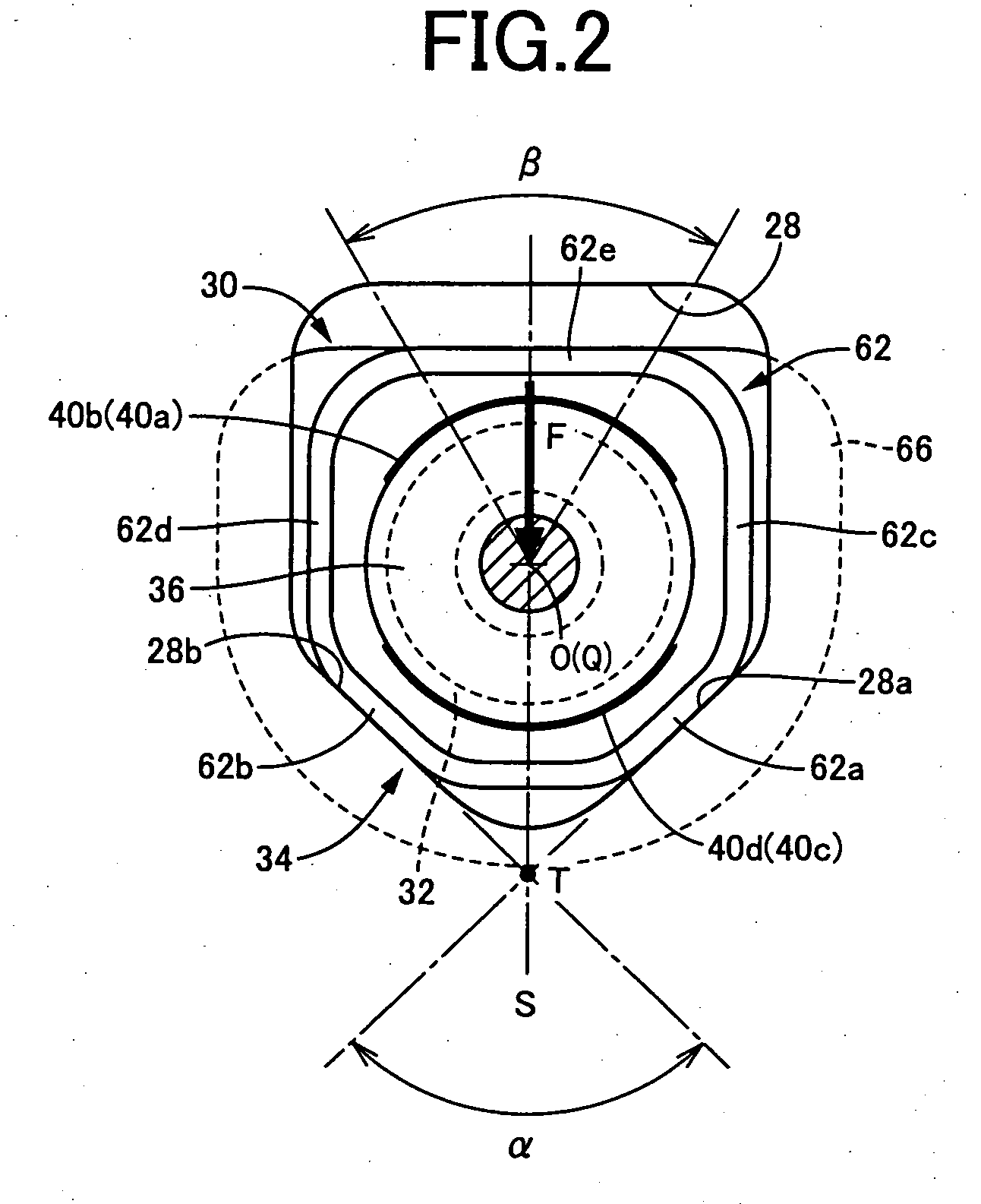
[0168]A load sensor 100 shown in FIG. 10 has the same fundamental structure as that of the embodiments set forth above, and includes the strain body 32, the case member 34 and the shaft-like member 36. However, the four strain resistance elements 102a to 102d placed in positions different from those of the embodiments described above. That is, the four strain resistance elements 102a to 102d are disposed in four area, demarcated with the neutral plane S and another plane passing across the axis, i.e., the centerline O, of the strain body 32 to be perpendicular to the neutral plane S, in a symmetrically positional relationship with respect to the neutral plane S. More particularly, the four strain resistance elements 102a to 102d are placed at four positions on the strain body 32 by approximately 90° so as to intersect with two straight lines passing across the centerline O (axis Q) of the sensor while crossing the neutral plane S at an angle of approximately 45°. The central positio...


PUM


Abstract

A load-sensor-equipped vehicle operating pedal device includes a load sensor (30) having a case member (34) formed with a pair of mounting wall portions (62a, 62b) converged in a convex shape at a predetermined apex angle α. The pair of mounting wall portions (62a, 62b) are held in surface contact with a pair of rest surfaces (28a, 28b), formed in a sensor-mounting hole (28) in a fixed and positioned state. Thus, even if a direction of an input load (reactive force), applied to a clevis pin (26) varies with an operating pedal 16 being progressively depressed, the pair of rest surfaces (28a, 28b) always bear the input load via the pair of mounting wall portions (62a, 62b). This suppresses the case member (34) from flexure deforming due to stress concentration. As a result, positional displacement of a sensor is prevented regardless of a variation in the direction of the input load, improving detecting precision.

Description

[0001]This application is based on Japanese Patent Application No. 2007-106377 and the Japanese Patent Application No. 2007-330823, and contents thereof is incorporated herein.BACKGROUND OF THE INVENTION[0002]1. Field of the Invention[0003]This invention relates to operating devices such as vehicle operating pedal devices or the like, and more particularly, to improvement of a load-sensor-equipped operating device having a load sensor for electrically detecting an operating force.[0004]2. Description of the Related Art[0005]Load-sensor-equipped operating devices have heretofore been known with one type including (a) an operating member displaceably operate; (b) a reactive member; (c) at least one pivotably connecting section; and (d) a load sensor. An operating force of the operating member is transmitted to the reactive member, on which a reactive force acts according to operating force. At least one pivotably connecting section is interposed between the operating member and the re...

Claims


Application Information

Patent Timeline
Patent Type & Authority Applications(United States)
IPC IPC(8): G05G1/30
CPCB60T7/042G01L5/225Y10T74/2054Y10T74/20888Y10T74/20528
Inventor FUJIWARA, NOBORU
Owner TOYODA IRON WORKS CO LTD
Why Eureka
Try Eureka