High voltage electrical connectors

Inactive Publication Date: 2008-10-09
LHV POWER
View PDF9 Cites 15 Cited by
  • Summary
  • Abstract
  • Description
  • Claims
  • Application Information

AI Technical Summary

Benefits of technology

[0007]It is the primary object of the present invention to provide a high voltage connector arrangement having improved performance and reduced cost for connecting high voltage wires in a simple and cost effective manner.
[0008]Another object of this invention is to create a method that will simplify the manufacturing of said high voltage connector units, with appropriate process and material, resulting in a low cost high voltage wire connector unit.
[0009]Another object of this invention is to create a resultant high voltage wire connector unit in which the wire connection is fully protected from the environment, and also, by the use of the proper techniques, the high voltage wires inside are fully encapsulated and insulated from each other, preventing internal arcing that would damage the parts.
[0010]The present low cost gas and liquid tight high voltage electrical connector invention is novel in that it has no dedicated male portion of the connector. Therefore it is desirable to integrate the high voltage wire itself as it becomes the male portion of the connector, saving significant parts cost. The wire may or may not have an added “pin” on the end of the wire to contact the female portion of the connector.
[0012]In a preferred high voltage wire splice embodiment, the system provides an inexpensive and expedient means to join or repair high voltage wires post installation. Generic watertight cord grips are used on the outside of the connector body as an environmental seal around a variety of high voltage wire diameters.
[0015]A third alternate embodiment of the novel low cost gas and liquid tight high voltage electrical connectors utilizes silicone dielectric grease that may be applied at the contact area and the seal area to enhance corona free operation at very high voltages. This use of dielectric grease at the contact point is highly advantageous with extremely high voltages.

Problems solved by technology

Connecting high voltage electricity from a power supply source device to a load has long been problematic, as voltages above about 300V may cause air surrounding the conductor to break down, or ionize, into damage-causing corona and arcing.
They are as such relatively expensive, pricing them out of range of the typical low cost high voltage electrostatic or other high voltage product application.
These connectors tend to be expensive and space consuming.

Method used


Image

  • High voltage electrical connectors
  • High voltage electrical connectors
  • High voltage electrical connectors

Examples


Embodiment Construction

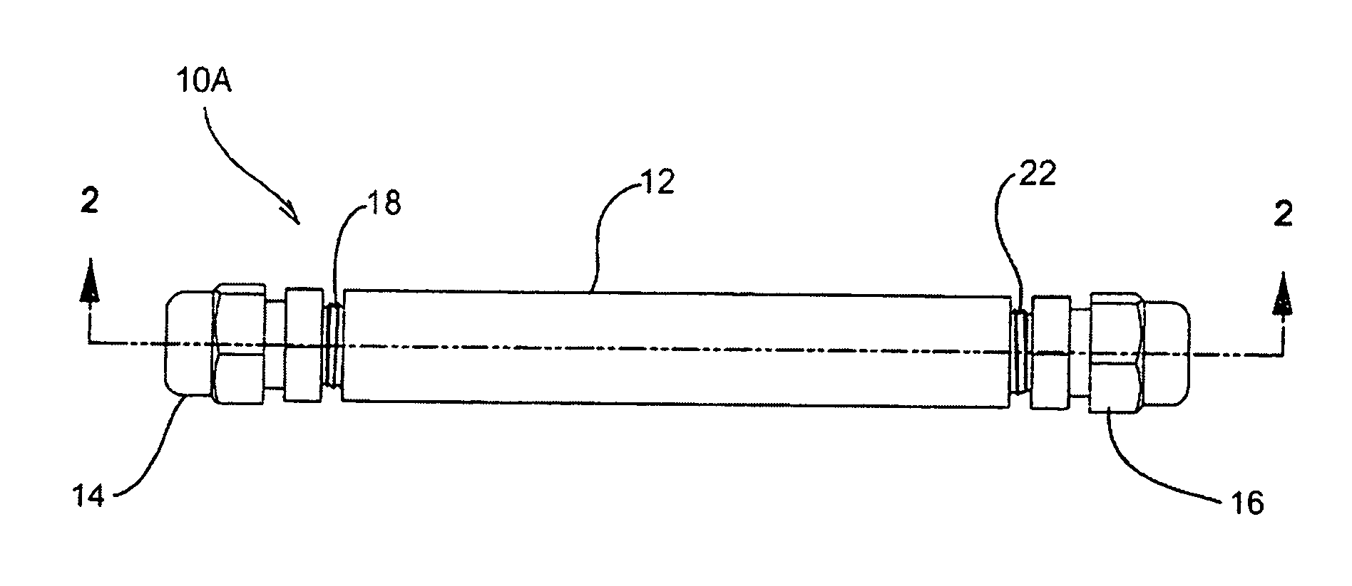
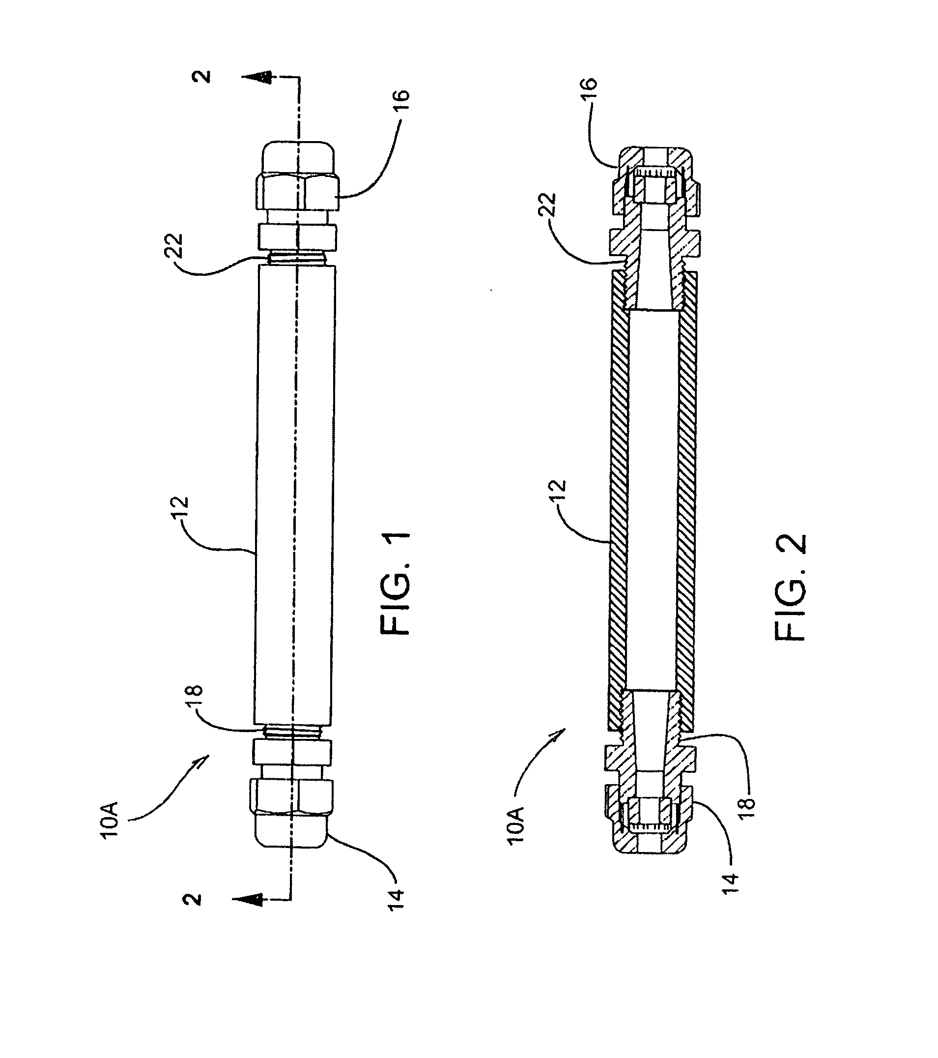
[0028]Referring now to FIG. 1, FIG. 1 depicts a side elevational view of a double ended high voltage splice connector device 10A. The connector housing 12 is attached to a gland 18 and 22, at each end. A compression nut 14 and 16 is mounted at the distal portions of the connector housing 12 by the glands 18 and 22. This unit is designed for non-encapsulated operation. Also, this double-ended high voltage splice connector device 10A is optimally suited for repair applications.

[0029]FIG. 2 depicts a cross-sectional view of the high voltage connector 10A illustrating the compression nuts 14 and 16 and the double ended connector housing 12 with gland bodies 18 and 22, in greater detail, constructed in accordance with the present invention. The threaded portions of the connector housing 12 accept the threaded portions of each of the glands 18 and 22.

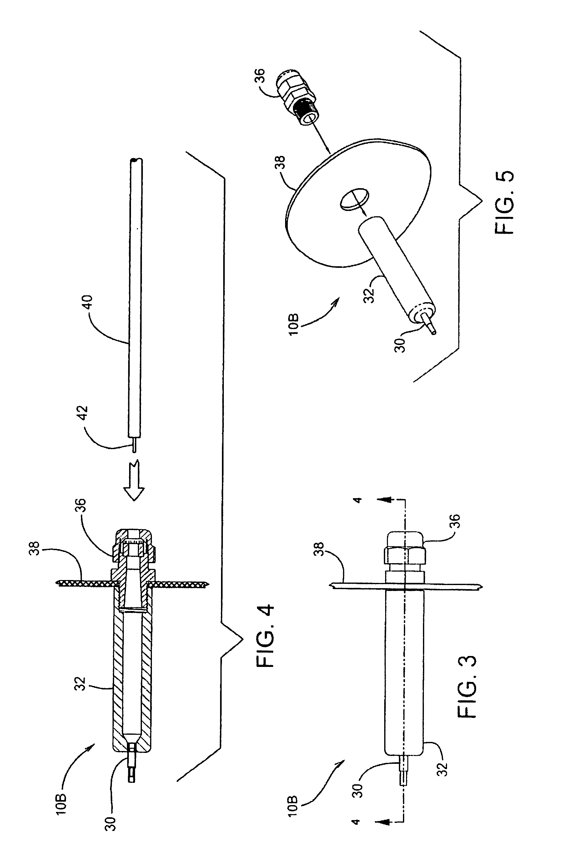
[0030]FIG. 3 is a side elevational view of a panel mount high voltage connector device 10B that has the female socket pin 30 encapsulated or...


PUM


Abstract

The present invention is directed to a connector housing for high voltage wires, either single ended or double ended with an integrated connector. Other features of the present invention include integration of a deep recessed high voltage connector contact for an arc and leakage resistant high voltage connection point, use of a female socket pin embedded at the base of the connector. The socket pin is co-molded into the connection end of the body, or it is co-molded or press fitted into a hole at the end of the connector housing.

Description

[0001]This US Non-provisional patent application claims the benefit of U.S. Provisional Patent Application Ser. No. 60 / 922,168 filed on Apr. 6, 2007.FIELD OF THE INVENTION[0002]The present invention generally relates to the field of high voltage connectors for the purpose of connecting high voltage electricity from a power supply source device to a load. More specifically, this patent deals with cost effective high voltage connectors for this purpose, and relates to a convenient and expedient means to join or repair high voltage wires post installation in a cost effective manner.BACKGROUND OF THE INVENTION[0003]An accepted definition of the term “high voltage” is any voltage over 42 volts (V). This level has been established by worldwide safety agencies as the level at above which normal dry human skin contact may result in injury. Typical “high voltage” power supplies in the electronics realm operate in the thousands of volts area; especially in the electrostatics industries, where...

Claims


Application Information

Patent Timeline
IPC IPC(8): H01R4/60
CPCH01R13/5216H01R13/53
Inventor WING, KENNETH E.CARROLL, SCOTT T.
Owner LHV POWER
Why Eureka
Try Eureka