
Roller Retainer

Active Publication Date: 2008-10-09
HIWIN TECH
View PDF9 Cites 0 Cited by
  • Summary
  • Abstract
  • Description
  • Claims
  • Application Information

AI Technical Summary

Benefits of technology

[0015]The primary objective of the present invention is to provide a roller retainer, which is less likely to fall off and can prevent the rollers from jamming, thus ensuring smooth circulation of the rollers.
[0016]The second objective of the present invention is to provide a roller retainer, which can prevent the rollers from contacting each other and prevent the non-loading surfaces of the rollers from colliding with and rubbing against the track.
[0018]To obtain aforementioned objectives, the roller retainer mounted on the rollers comprises a first guiding frame and a second guiding frame that are integrally connected with each other in a vertically staggered manner. The first guiding frame and the second guiding frame are located along two diagonals of each roller respectively. Additionally, the thickness of the first guiding frame and the second guiding frame is utilized to keep the space between the non-loading surfaces and the track, so as to prevent the non-loading surfaces from colliding with the surface of the track, avoid the unnecessary collision and attrition. Moreover, the roller retainer can further keep the space between each roller.
[0019]Thereby, the first guiding frame and the second guiding frame that are vertically connected with each other in the staggered manner in accordance with the present invention can prevent the rollers from contacting each other in various operational conditions (including the overturn operational process during the re-circulation of the rollers). The non-loading surfaces of the rollers are restricted by the first guiding frame and the second guiding frame, so the rollers are difficult to incline and fall off when bearing the torque, thus effectively reducing the noise and improving the operation stability and so on.
[0020]It is important that, the roller retainer in accordance with the present invention is introduced by the research efforts of experiments and the tests, and it is found that if be made of plastic or rubber which has flexibility, the roller retainer will exert a relatively fine effect. In addition, the thickness of first guiding frame and the second guiding frame need not be excessively thick, because the roller can be stably positioned by the restriction of the first guiding frame and the second guiding frame that are vertically connected with each other in the staggered manner. Consequently, the roller retainer in accordance with the present invention will not make the space between each roller excessively great, the track can be adequately disposed with a predetermined number of rollers, and the load capability of the product can also be kept

Problems solved by technology

First, since the rollers 10 are positioned on the tooth-shaped track 13 between the roller screw and the nut, the screw and the nut will not only contact the loading surfaces of the roller 10, but also contact the non-loading surfaces of the rollers, thus causing the collision and the friction therein, and influencing the moving direction of the rollers 10, as a result, it cause attrition and stress loss.
Second, in order that the space rings 12 disposed on the rollers 10 can run smoothly along the tack 13 between the roller screw and the nut, the track 13 should be additionally formed with a groove 14. Since the groove 14 is formed in the loading surface of the rollers 10, the contacting length of the rollers 10 is reduced and the load capability of the product is consequently decreased.
But the roller will apply a torque to the stopping annular retainer 16 while rotating, consequently, the roller 15 will incline to the non-loading surfaces thereof, thus the stopping annular retainer 16 is difficult to position, and likely to fall off, this technology is quite easy to cause the stopping annular retainer to fall off and the rollers to be jammed.

Method used


Image

  • Roller Retainer
  • Roller Retainer
  • Roller Retainer

Examples


Embodiment Construction

[0031]The present invention will be clearer from the following description when viewed together with the accompanying drawings, which show, for purpose of illustrations only, the preferred embodiment in accordance with the present invention.

[0032]Referring to FIGS. 4-7, a roller retainer in accordance with a preferred embodiment of the present invention is characterized in that:

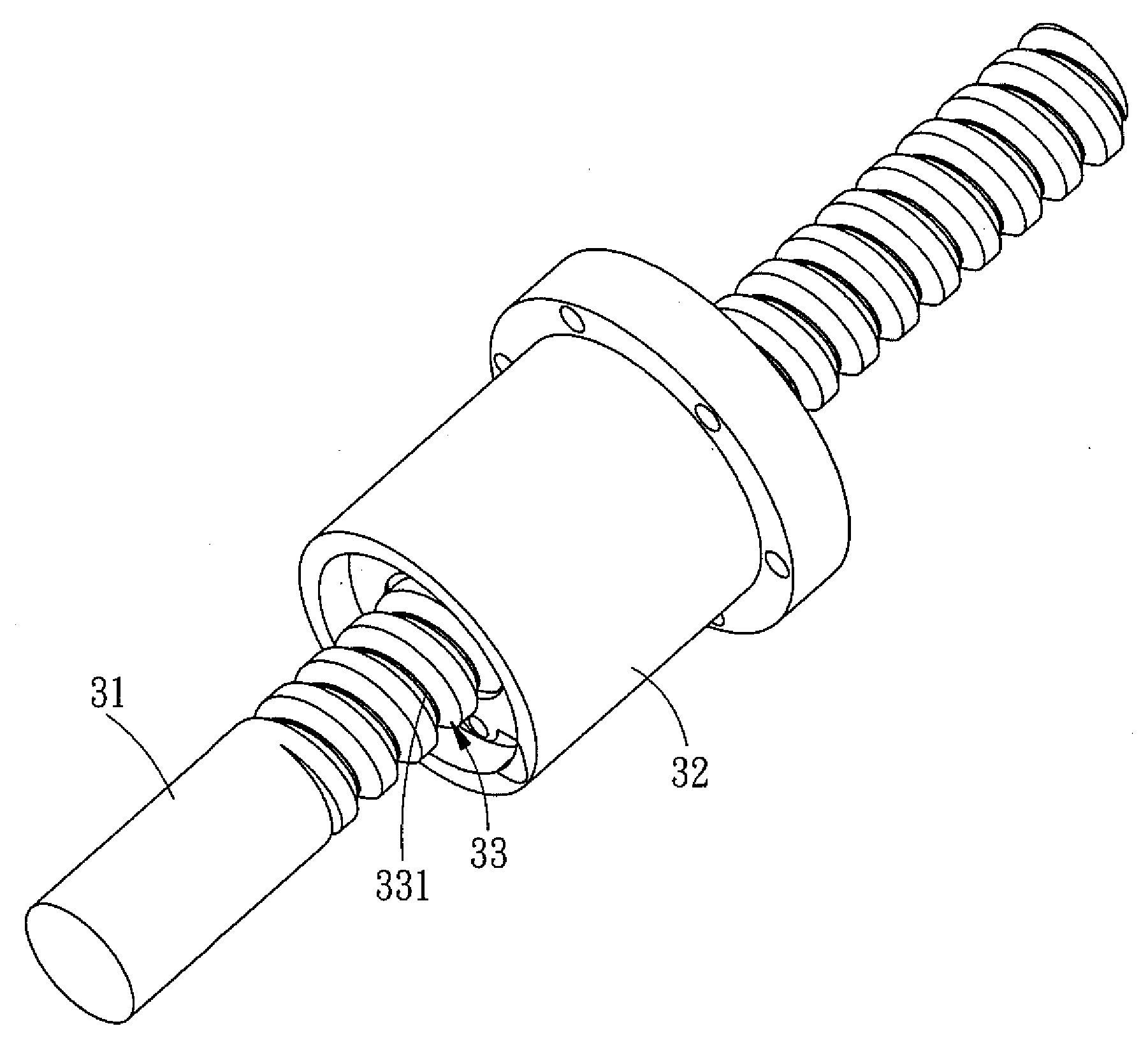
[0033]A roller retainer 20 is disposed on a roller 30, the roller 30 is arranged in a track 33 defined by a screw 31 and a nut 32, and a guiding groove 331 is formed in the mid portion of the track 33.

[0034]The roller retainer 20 comprises a first guiding frame 21 and a second guiding frame 22 that are integrally connected with each other in a vertically staggered manner, and the first frame 21 and the second frame 22 are frame-shaped structures located along the two diagonals of the roller. The first guiding frame 21 is located along one diagonal of the roller 30, and the second guiding frame 22 is located a...


PUM


Abstract

A roller retainer mounted on a roller comprises a first guiding frame and a second guiding frame that are integrally connected with each other in a vertically staggered manner. The first guiding frame and the second guiding frame are located along the two diagonals of the roller respectively. The thickness of the first guiding frame and the second guiding frame is utilized to keep the space between the two non-loading surfaces of roller and a track. The roller retainer can further keep the space between each roller. Thereby, the roller retainer can prevent the rollers from contacting each other; the loading surfaces can still contact the track and the non-loading surfaces are prevented from colliding with and rubbing against the track, thus reducing the noise and ensuring the moving direction.

Description

BACKGROUND OF THE INVENTION[0001]1. Field of the Invention[0002]The present invention relates to a retainer, and more particularly to a roller retainer, which can prevent the rollers from contacting each other, and keep the non-loading surfaces of the rollers from colliding with and rubbing against the track while the loading surfaces of the rollers can still contact the track, consequently reducing the noise and assuring the moving direction.[0003]2. Description of the Prior Art[0004]Linear guideway and roller screw are used more and more widely in modern industries. In addition to its high precision transmission performance, the linear guideway and roller screw also have many other advantages, such as low friction loss, high ratio of energy conversion, low noise, high rigidity and wear-resistance. Therefore, it is self-evident that the linear guideway or the roller screw is very important to various industrial mechanisms.[0005]Normally, rollers are one of the frequently used rolli...

Claims


Application Information

Patent Timeline
IPC IPC(8): B60P1/52
CPCF16C33/51Y10T74/19777F16H25/2247
Inventor PAN, HUNG-SUNGTSOU, CHIEN-WEI
Owner HIWIN TECH
Learn More