
Color display system

a display system and color technology, applied in the field of color display apparatuses, can solve the problems of difficult to improve the brightness corresponding to the picture data, the control of the brightness of each color is still limited, and the display system has limitations for further improvement of display qualities, so as to improve the color balance and brightness of the display picture

Inactive Publication Date: 2008-10-09
SILICON QUEST KABUSHIKI KAISHA +1
View PDF35 Cites 5 Cited by
  • Summary
  • Abstract
  • Description
  • Claims
  • Application Information

AI Technical Summary

Benefits of technology

This solution enhances brightness and gray-scale resolution by dynamically controlling color display times, allowing for improved image quality with increased gray-scale levels and flexible color balance, capable of displaying images with up to 768 or more gray-scale levels per color.

Problems solved by technology

However, such display systems still have limitations for further improvement of display qualities as will be further discussed below.
It is difficult to improve the brightness corresponding to the picture data.
The control of the brightness of each color is still limited due to the limitation that the brightness control cannot be directly corresponding to the characteristic of the color combination of input picture data.
The quality of the image display is degraded due to the limitation that a dynamic brightness control of each color cannot be performed.
Furthermore, the limitation of not able to flexibly control the brightness of each color in each display frame further limits the resolution of the gray-scale levels

Method used


Image

  • Color display system
  • Color display system
  • Color display system

Examples


Embodiment Construction

[0047]The embodiments of the present invention are described in details below with reference to the drawings.

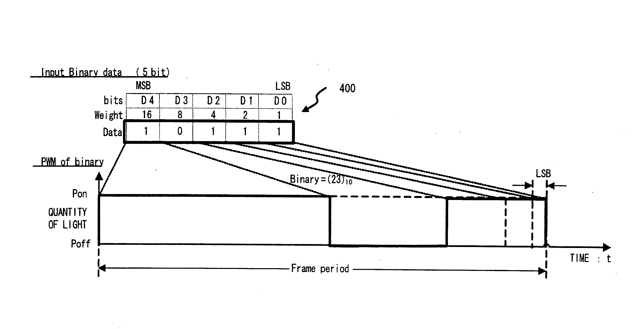
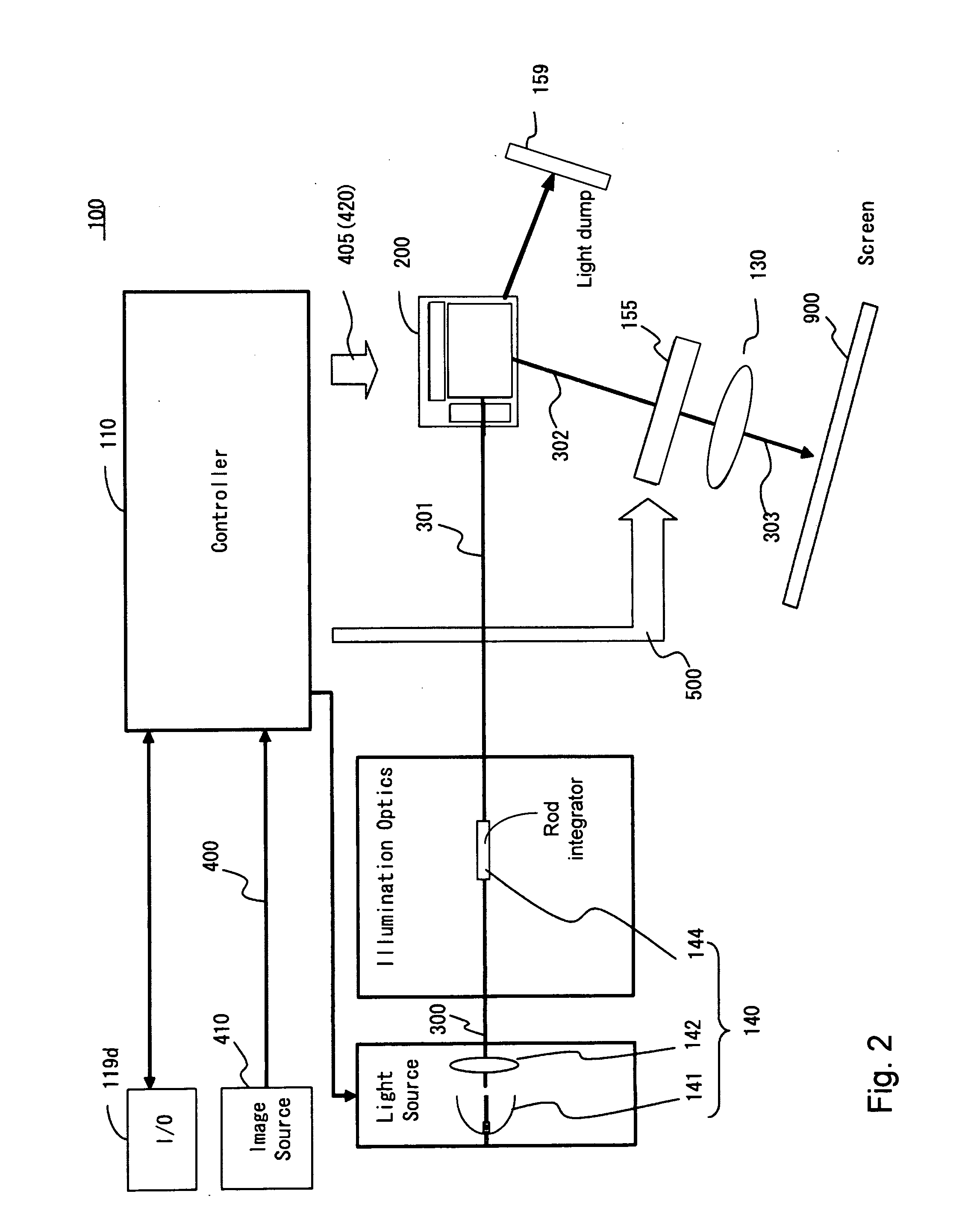
[0048]FIG. 2 is a functional block diagram for showing the configuration of the color display device for carry out the color display methods according to embodiments of the present invention. FIG. 3 is a block diagram for showing an exemplary configuration of a control system of a projection display device of the present invention. FIG. 4 is a cross sectional view of a mirror element for showing an exemplary configuration of each pixel unit of a spatial light modulation element configuring a projection display device as an embodiment of the present invention. FIGS. 5, 6, and 7 are timing diagrams for showing exemplary operation sequences of the color display device according to an embodiment of the present invention.

[0049]FIG. 2 shows a color display device 100 includes a spatial light modulator 200, a control unit 110, a projective optical system 130, and a light source opti...


PUM


Abstract

A color display device including: at least one spatial light modulation element forming a display picture by modulated light obtained by modulating illumination light, a color sequential light generation device changing in a time series the illumination light or the modulated light into multiple groups of different color lights in one frame of a display period of the display picture, a control device controlling the spatial light modulator, and a color sequential light generation device based on the input picture data. The control device controls the spatial light modulator and the color sequential light generation device to change the ratio of the display time of each color of the reflected light time-shared in the display period of the frame depending on the character and / or the set value of the input picture data.

Description

[0001]This application is a Non-provisional application claiming a Priority date of Mar. 2, 2007 based on a previously filed Provisional Application 60 / 904,564 filed by the common Applicants of this Application and the disclosures made in Provisional Application 60 / 904,564 are further incorporated by reference.BACKGROUND[0002]1. Field of Invention[0003]The present invention relates to a color display apparatuses. More particularly, this invention relates to color image display systems implemented with an effective color display technique for controlling display light for each color of the primary colors.[0004]2. Prior Art[0005]Color image display systems are known and commonly implemented with color displays using three primary colors of red, green and blue. However, such display systems still have limitations for further improvement of display qualities as will be further discussed below.[0006]U.S. Pat. No. 5,448,314 discloses a technique for displaying a color image by projecting ...

Claims


Application Information

Patent Timeline
Patent Type & Authority Applications(United States)
IPC IPC(8): G09G5/10
CPCH04N9/3111H04N9/312H04N9/3155H04N9/3164H04N9/3197
Inventor ENDO, TAROISHII, FUSAOMAEDA, YOSHIHIROICHIKAWA, HIROTOSHINISHINO, HIROKAZU
Owner SILICON QUEST KABUSHIKI KAISHA
Learn More