Selective envelope modulation enabling reduced current consumption

a selective envelope and current consumption technology, applied in the field of envelope modulation, can solve the problems of reducing the operation rate and power consumption, and achieve the effects of reducing the current consumption, reducing the power consumption of the signal, and reducing the power consumption

Active Publication Date: 2008-10-09
APPLE INC
View PDF2 Cites 6 Cited by
  • Summary
  • Abstract
  • Description
  • Claims
  • Application Information

AI Technical Summary

Benefits of technology

[0008]In implementations of the system, the control signal controls the rate of operation of the amplitude modulation path, such that a reduced rate of operation results in lower power consumption. Preferably, the system is a polar modulation system.
[0009]A method of efficient signal modulation receives an amplitude signal and a phase signal. The method modulates a carrier signal by using one of the amplitude signal and the phase signal to generate a modulated signal. The method reduces power consumption required by the modulator such that a power savings results without substantially changing the modulated signal. In a particular embodiment, the method receives a control signal that adjusts the rate of the modulating, and in some embodiments, the control signal includes a clock rate.
[0010]Preferably, the amplitude signal is received by an amplitude path, the phase signal is received by a phase path, and reducing power consumption comprises reducing a current supplied to the amplitude path. In these embodiments, the amount of power consumption is related to the rate of operation of the amplitude path and reducing power consumption includes reducing the rate of operation of the amplitude path. Some embodiments advantageously control the modulating. For instance, typically, the amount of power consumption is related to the rate of the modulating, and reducing the power consumption includes reducing the rate of the modulating.

Problems solved by technology

In implementations of the system, the control signal controls the rate of operation of the amplitude modulation path, such that a reduced rate of operation results in lower power consumption.

Method used


Image

  • Selective envelope modulation enabling reduced current consumption
  • Selective envelope modulation enabling reduced current consumption
  • Selective envelope modulation enabling reduced current consumption

Examples


Embodiment Construction

[0019]In the following description, numerous details and alternatives are set forth for purpose of explanation. However, one of ordinary skill in the art will realize that the invention can be practiced without the use of these specific details. In other instances, well-known structures and devices are shown in block diagram form in order not to obscure the description of the invention with unnecessary detail.

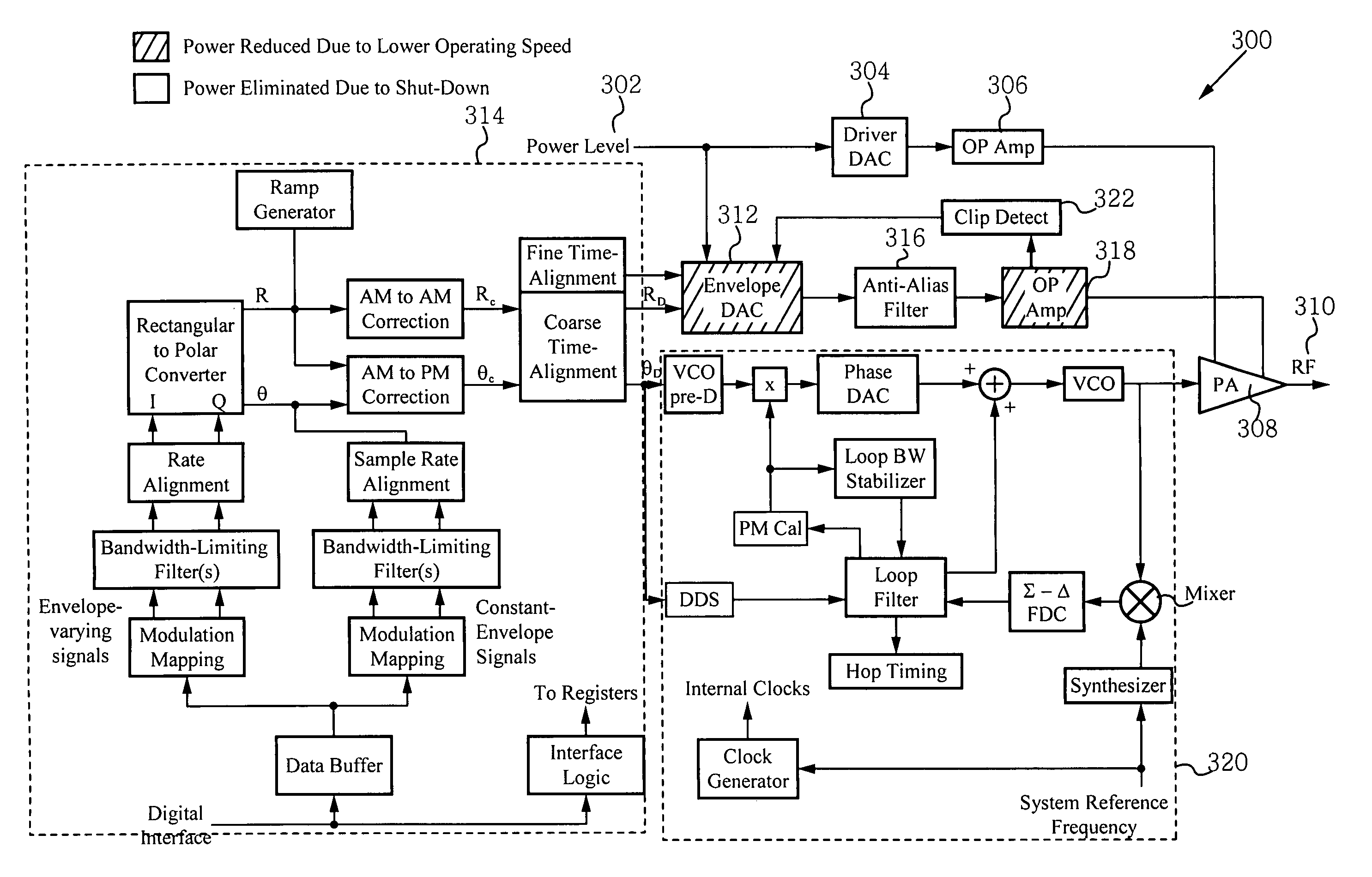
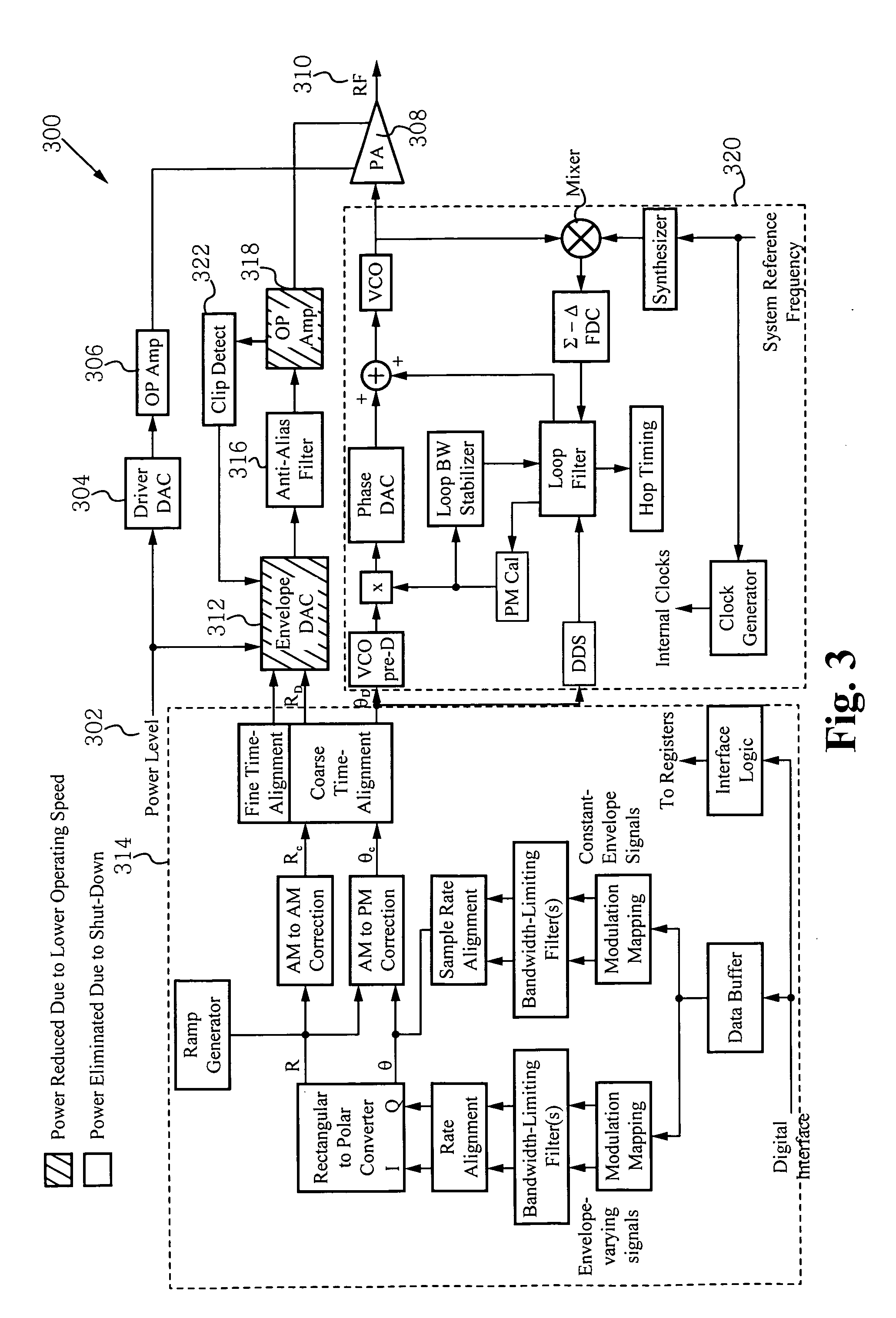
[0020]In modern high capacity wireless communication systems, many signals chosen for transmission use a combination-of amplitude modulation (AM) and phase modulation (PM) to minimize the signals' occupied bandwidth. These signals generally use linear circuitry in their implementation, and implement the combined modulation using quadrature (I&Q) techniques.

[0021]Some embodiments of the invention employ a polar transmitter that includes an amplitude modulation path and a phase modulation path. When this type of polar transmitter is used, the amplitude modulation path can selecti...


PUM


Abstract

A modulation system includes an amplitude modulation path and a phase modulation path coupled to the amplitude modulation path. One of the amplitude modulation path and the phase modulation path receive a reduced current such that the reduced current reduces power consumption by the system. Preferably, the amplitude modulation path receives the reduced current. The amplitude modulation path has a first set of components and a second set of components. The first set of components consumes less power by using slower operation. The second set of components consumes less power by effectively not operating, or being turned off.

Description

RELATED APPLICATIONS[0001]This Patent Application claims priority under 35 U.S.C. §119(e) of the co-pending, co-owned U.S. Provisional Patent Application No. 60 / 922,261, filed Apr. 5, 2007, and entitled “SELECTIVE ENVELOPE MODULATION ENABLING REDUCED CURRENT CONSUMPTION” which is also hereby incorporated by reference in its entirety.FIELD OF THE INVENTION[0002]The present invention is related to the field of envelope modulation, and is more specifically directed to selective envelope modulation enabling reduced current consumption.BACKGROUND[0003]The 3GPP standard TS25.101 (section 6.6.2.2) sets the following requirements on adjacent channel leakage power ratio measurement for mobile phones: Adjacent channel leakage power ratio (ACLR) is the ratio of the transmitted power to the power measured after a receiver filter in the adjacent channel(s). Both the transmitted power and the received power are measured with a filter that has a root-raised cosine (RRC) filter response with roll-o...

Claims


Application Information

Patent Timeline
Patent Type & Authority Applications(United States)
IPC IPC(8): H03C3/38H03C1/00
CPCH03C5/00
Inventor BIEDKA, THOMAS E.LIANG, PAUL CHENG-PODO, GARY L.
Owner APPLE INC
Why Eureka
Try Eureka