
Method and apparatus for measuring the output current of a switching regulator

Inactive Publication Date: 2008-10-09
APPLE INC
View PDF3 Cites 173 Cited by
  • Summary
  • Abstract
  • Description
  • Claims
  • Application Information

AI Technical Summary

Benefits of technology

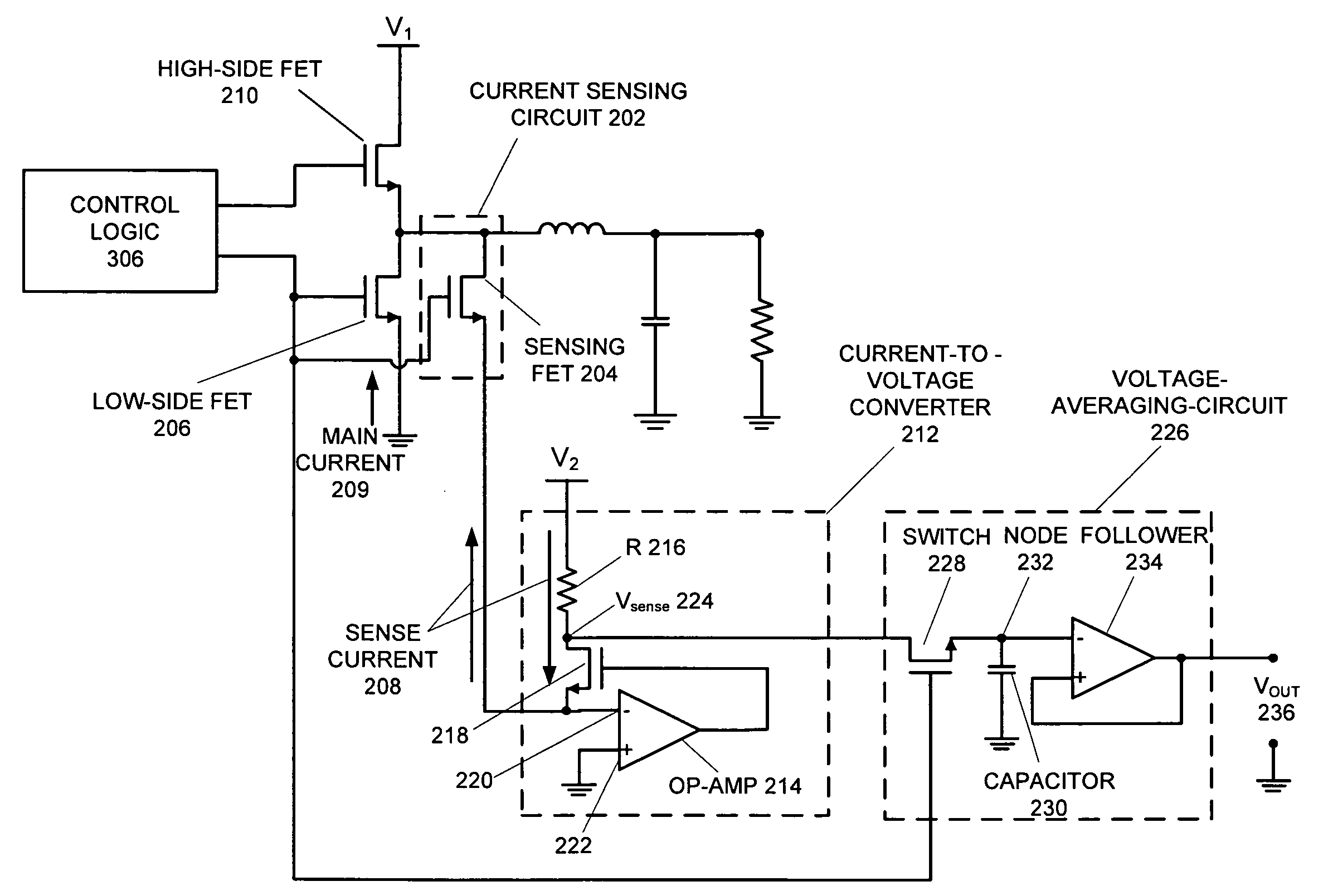
[0016]In a variation on this embodiment, the voltage-average-circuitry is configured to average the sense voltage input when the switch is activated by the control signal and is configured to maintain the average-sense-voltage when the switch is deactivated by the control signal, thereby facilitating tracking of the average-sense-voltage during a period of the control signal.

Problems solved by technology

These advances can be largely attributed to an exponential increase in the density and complexity of integrated circuits (ICs).
Unfortunately, in conjunction with this increase in computational power, power consumption and heat dissipation of ICs has also increased dramatically.
Increasing power consumption and associated heat dissipation creates serious challenges for power management and cooling in computing devices, especially for portable computers.
However, this technique can cause significant amount of dissipative loss on the current sensor because the entire output current flows through this current-sensing component.
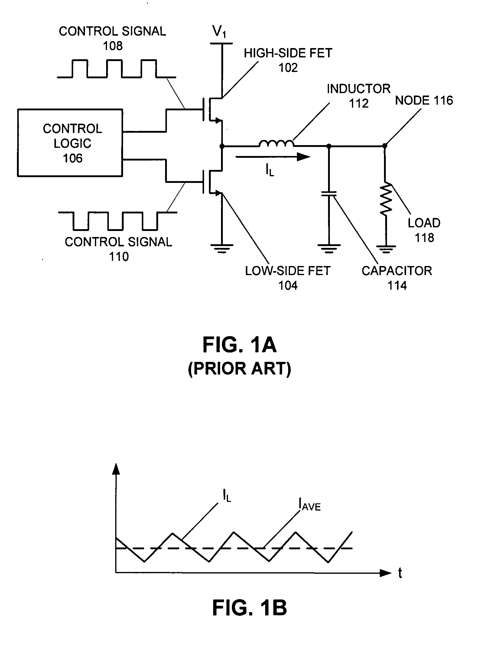
For example, one can obtain the output current by first measuring the voltage across inductor L and then computing the current by dividing the voltage by the resistance of inductor L. Unfortunately, the resistance of inductor L is typically not a constant and is difficult to measure.

Method used


Image

  • Method and apparatus for measuring the output current of a switching regulator
  • Method and apparatus for measuring the output current of a switching regulator
  • Method and apparatus for measuring the output current of a switching regulator

Examples


Embodiment Construction

[0023]The following description is presented to enable any person skilled in the art to make and use the invention, and is provided in the context of a particular application and its requirements. Various modifications to the disclosed embodiments will be readily apparent to those skilled in the art, and the general principles defined herein may be applied to other embodiments and applications without departing from the spirit and scope of the present invention. Thus, the present invention is not limited to the embodiments shown, but is to be accorded the widest scope consistent with the principles and features disclosed herein.

Overview

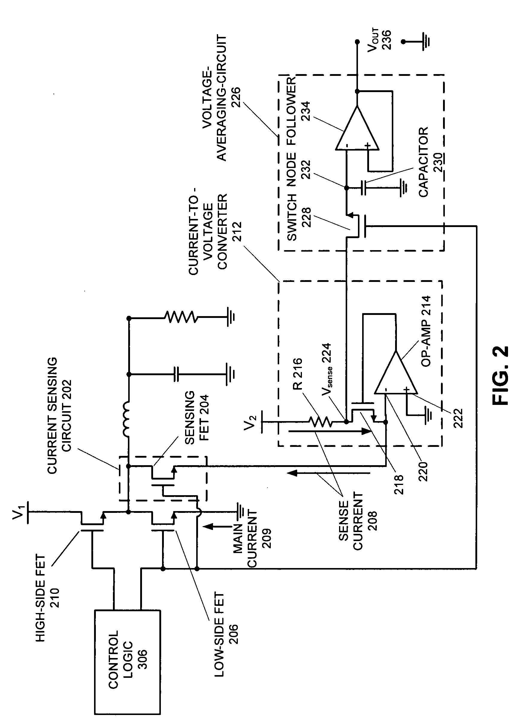
[0024]The present invention determines the real-time power consumption of an integrated circuit (IC) chip by measuring the average output current from the switching regulator that supplies power to the IC chip. Specifically, a current-sensing-circuit is used to bypass a tiny sense current from a main switching-regulator-output-current according to a p...


PUM


Abstract

One embodiment of the present invention provides an apparatus that measures the average-output-current produced by a switching regulator within an electronic device. The apparatus includes current-sensing-circuitry coupled to a switching field-effect-transistor (FET) within the switching regulator, wherein the current-sensing-circuitry is configured to bypass a small sense current from the conducting current of the switching-FET according to a sense ratio, wherein the conducting current is controlled by a control signal for the switching regulator. The apparatus also includes a current-to-voltage-converter coupled to the current-sensing-circuitry which is configured to convert the sense current into a sense voltage. The apparatus further includes voltage-averaging-circuitry which is configured to produce an average-sense-voltage from the sense voltage. This sense voltage is coupled to the input of the voltage-average-circuitry through a switch, which is gated by the control signal. The average-output-current of the switching regulator is indicated by the average-sense-voltage.

Description

BACKGROUND[0001]1. Field of the Invention[0002]The present invention relates to techniques for determining the power consumption of an electronic device, such as an integrated circuit (IC) chip. More specifically, the present invention relates to a method and apparatus for determining the power consumption of an electronic device by measuring an average output current generated by a switching regulator that supplies power to the electronic device.[0003]2. Related Art[0004]Rapid advances in computing technology presently make it possible to perform trillions of operations each second on data sets as large as a trillion bytes. These advances can be largely attributed to an exponential increase in the density and complexity of integrated circuits (ICs). Unfortunately, in conjunction with this increase in computational power, power consumption and heat dissipation of ICs has also increased dramatically.[0005]Increasing power consumption and associated heat dissipation creates serious ch...

Claims


Application Information

Patent Timeline
IPC IPC(8): G01R19/00
CPCG01R19/003G01R19/0092
Inventor SMITH, ERIC
Owner APPLE INC
Learn More