
Apparatus and method for cutting lawns using lasers

Inactive Publication Date: 2008-10-09
RENEWABLE THERMODYNAMICS LLC
View PDF24 Cites 13 Cited by
  • Summary
  • Abstract
  • Description
  • Claims
  • Application Information

AI Technical Summary

Benefits of technology

[0007]The present invention overcomes the problems associated with prior devices used for cutting lawns. It is no longer necessary to push or ride a lawn mower across the lawn. The present invention utilizes rotating laser light from fixed locations on the lawn to cut the grass.
[0011]The laser light need only have enough power such that it cuts through a single or a small number of blades of grass. As the light continues to sweep, multiple sweeps of the same area will gradually cut more blades of grass further from the laser head until the desired range is obtained. In this way, the power of the laser can be held to the lowest possible level consistent with cutting a single blade of grass or a small number of blades at one time. The variability of the surface of the ground requires variable length beams, which are achieved by varying the power level of the lasers. Where the ground surface is uneven, lower power is used to prevent the laser light from scalping the lawn or cutting the grass too high. By localizing the laser light emitted from the laser heads, a more even cut length is possible. Instead of using lower power, a lens system could be used which allows for the adjustment of the length of the laser beam, or its effective range. Alternatively, the laser heads could be replaceable such that a laser head which generates a laser beam of an appropriate length may be selected for the localized requirements on the land area.
[0014]To facilitate the safe operation of the system, motion sensors could be used to prevent or stop the generation of the laser beam when the motion sensor senses a predetermined amount of motion within or near the laser grid. With this feature, when an animal or person enters the lawn area covered by the matrix of laser heads, the system will prevent the generation of laser light. The motion detectors should, preferably, cover an area which extends beyond the property lines of the land which has the system installed. This would provide an early warning system that will safely result in laser shutdown before people or animals actually cross the property lines. In addition, rain sensors could be used to prevent the generation of a laser beam when it is raining.
[0015]The present invention may also be used to control insects. The laser light generated by the laser heads will be powerful enough to kill small flying insects such as mosquitoes and gnats. These insects frequently are found in the evening and at night flying just above a lawn or above a stationary body of water, such as a small pond. A laser head may be adapted such that it can kill these insects. The laser beam could be elevated a few inches above those used for cutting the lawn. Preferably, the beam of light would be wider and more diffuse than one designed to cut grass. The laser heads used for insect elimination could be combined with the ones for cutting grass or could be part of an independent plurality of laser heads. For example, when used over water, the insect elimination lasers will be used without the vegetation cutting lasers. In addition, the insect killing laser beams could be emitted much higher above the ground than the vegetation cutting lasers so that the laser light can sweep large areas above the land, well above the level of the top of the vegetation.

Problems solved by technology

Each laser head may rotate up to 360 degrees, or the amount of its rotation may be limited so that the laser light does not extend to objects, such as flowerbeds, trees or other vegetation, in an undesirable manner.

Method used


Image

  • Apparatus and method for cutting lawns using lasers
  • Apparatus and method for cutting lawns using lasers
  • Apparatus and method for cutting lawns using lasers

Examples


Embodiment Construction

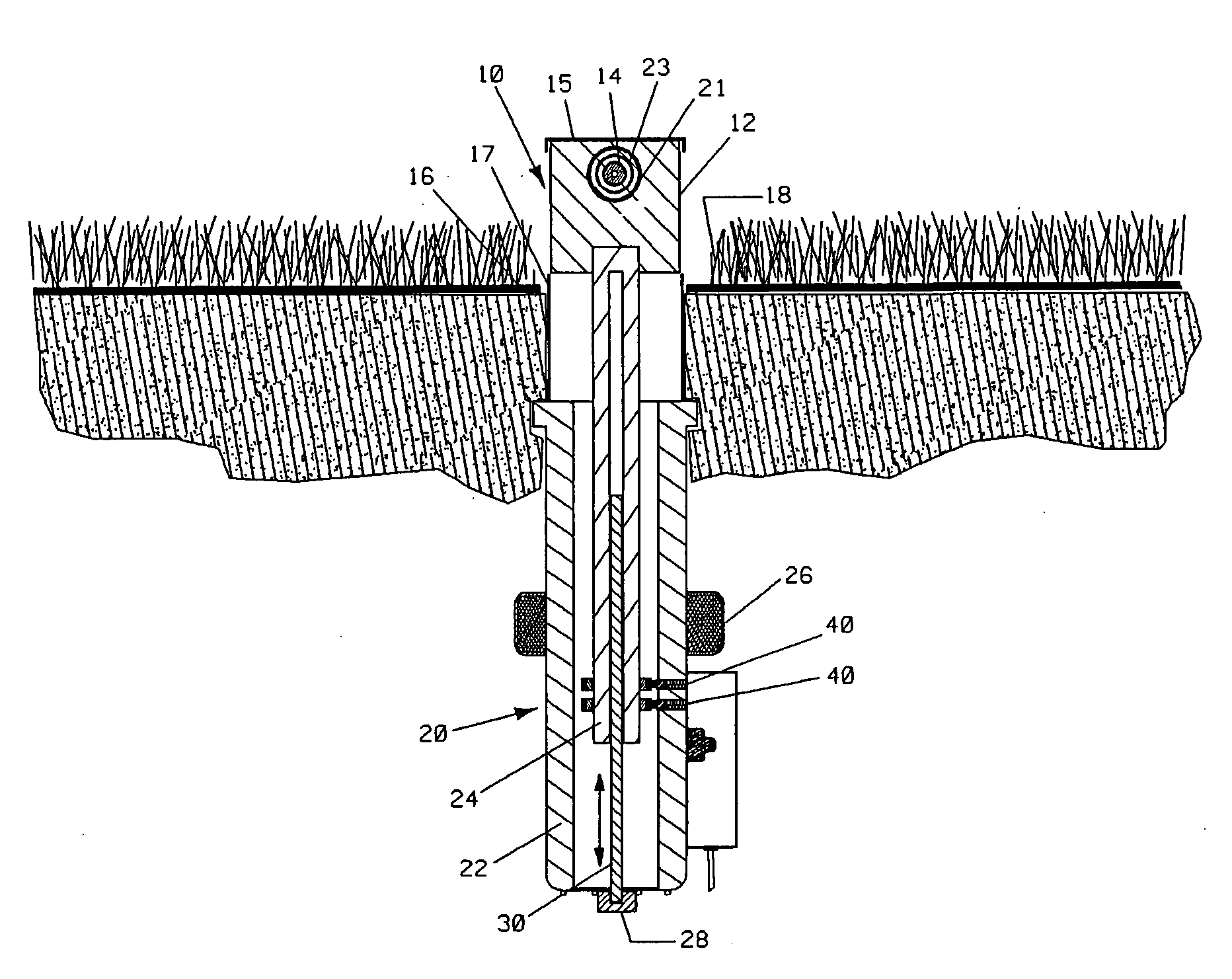
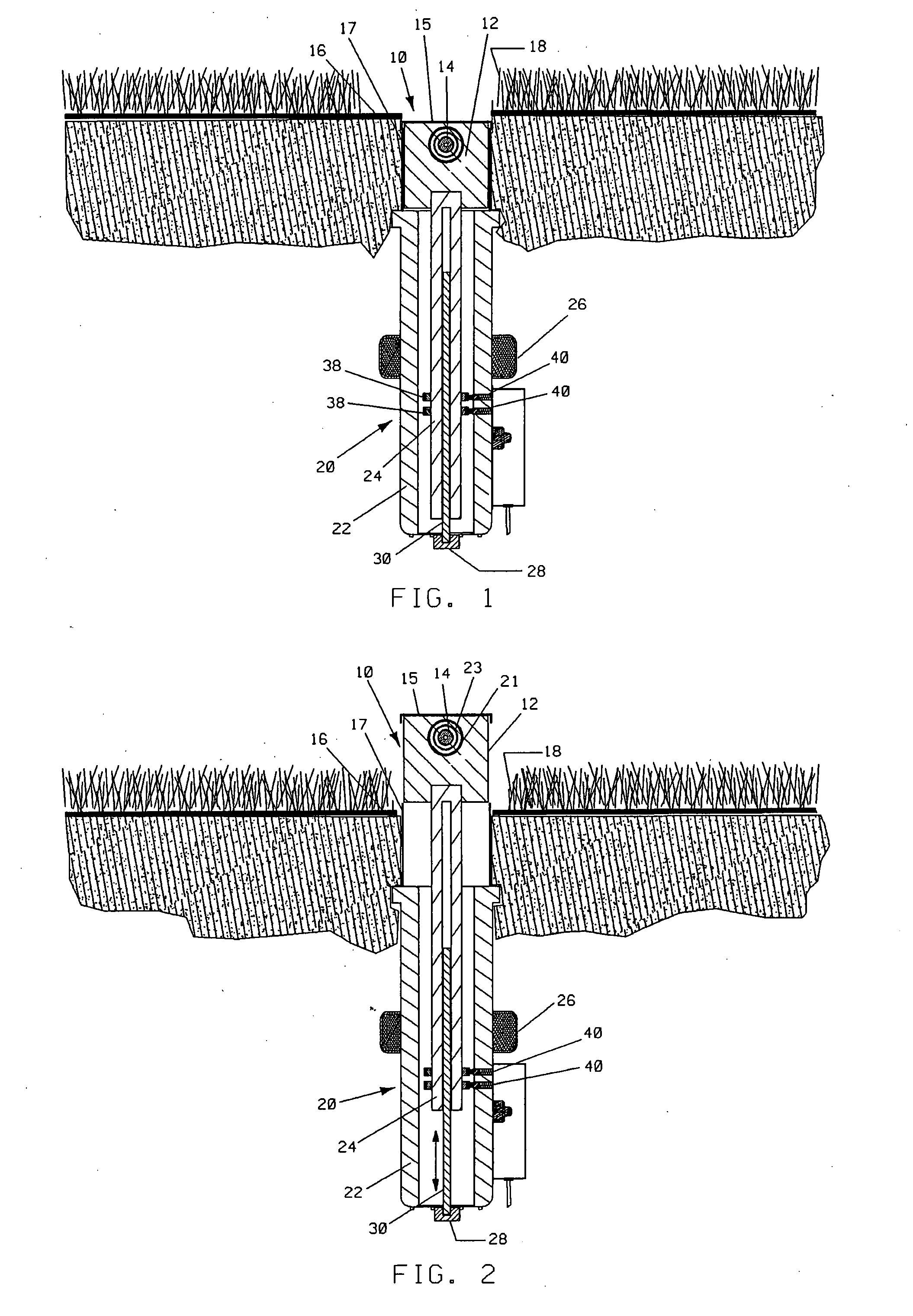
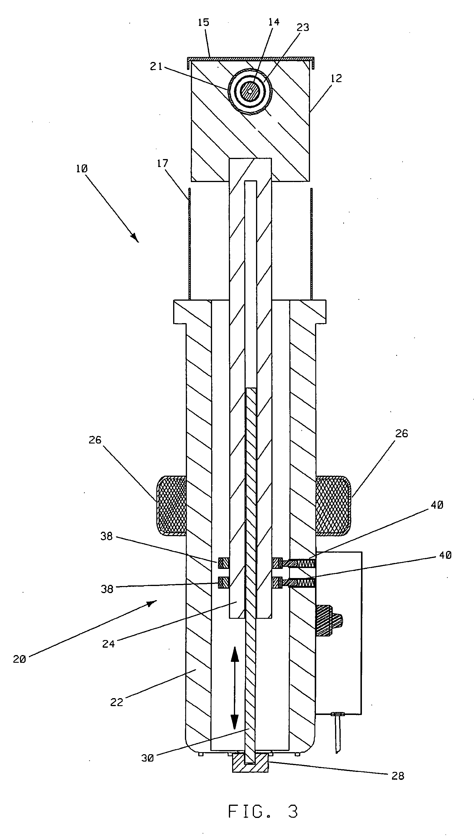
[0036]FIGS. 1-18 illustrate the present invention. In FIG. 1, a cross-sectional view of a single laser assembly 10 is shown. The assembly 10 includes a pop-up laser head 12 with a semiconductor diode laser 14. When not in use, the pop-up laser head 12 is flush with the ground 16 (or below grade) at the base of the grass 18. A cap 15 and cylinder 17 protect the laser head 12 when it is below ground 16. Beneath the ground level 16 is the laser head mounting assembly 20 which includes a shell 22, pin 24 and solenoid coil 26. The pin 24 is mounted for translational movement in the vertical direction. The pin 24 is also mounted for rotational movement caused by motor 28 turning shaft 30. Brushes 40 and rings 38 provide electrical energy from a power supply 34 to power the semiconductor laser 14. Wires (not shown) provide electrical power to the solenoid 26 and the motor 28.

[0037]When electrical current is sent from the power supply 34 to the solenoid 26, it is energized and the pin 24 mo...


PUM

PropertyMeasurementUnit
Electric potential / voltageaaaaaaaaaa
Distanceaaaaaaaaaa
Lengthaaaaaaaaaa

Abstract

The laser lawn cutting system of the present invention consists of an array or grid of laser heads distributed across a lawn. The laser heads may be permanently fixed above the surface of the lawn, or preferably mounted underneath the surface of the lawn and designed to pop up at the time of cutting. If mounted underneath the surface of the lawn, solenoids may be used to move the laser heads above the surface. Other mechanical devices could also be used to cause the laser heads to move above the surface of the lawn. Preferably, the laser heads will be distributed across the lawn in a grid or matrix, such that the laser light generated by the rotating laser head sweeps across the lawn in overlapping arcs to cut the vegetation. The system may also be used to melt snow or kill insects.

Description

FIELD OF THE INVENTION[0001]The present invention relates to an improved apparatus and method for cutting vegetation. More particularly, the present invention relates to an apparatus and method for cutting lawns using laser light.BACKGROUND OF THE INVENTION[0002]The vast majority of suburban houses and many urban houses in the United States have yards covered with grass. These grass yards or lawns must be mowed on a regular basis to keep the grass at a desirable height. Furthermore, commercial property, parks, golf courses and other maintained property is often covered with grass. Currently, most lawns and maintained properties are mowed using gasoline or electric powered lawn mowers, riding mowers or lawn tractors which include spinning steel blades. The owner, or someone hired by the owner, either pushes or rides the mowers across the lawn to cut the grass, which is a time consuming process. In addition, the use of gasoline powered lawnmowers uses a significant amount of fossil fu...

Claims


Application Information

Patent Timeline
IPC IPC(8): A01D34/01
CPCA01D34/015A01D34/01
Inventor IDE, RICHARD J.HOFFMAN, GARY P.IDE, NANETTE F.
Owner RENEWABLE THERMODYNAMICS LLC
Learn More