
Abdominal impedance measurement apparatus

a technology of impedance measurement and abdominal belt, which is applied in the field of abdominal belt impedance measurement apparatus, can solve the problems of inconvenient winding of the belt around the abdomen, inconvenient use, and inability to arrange the impedance measurement electrodes at such reference positions, and achieves a high degree of reproducibility and convenient arrangemen

Inactive Publication Date: 2008-10-02
TANITA CORP
View PDF5 Cites 16 Cited by
  • Summary
  • Abstract
  • Description
  • Claims
  • Application Information

AI Technical Summary

Benefits of technology

[0011]Accordingly, the present invention provides an abdominal impedance measurement apparatus that enables the electrodes to be easily arranged at the abdomens of human subjects so that bioimpedance can be measured with a high degree of reproducibility.
[0013]With such a structure, since the electrode supporting member includes segments connected mutually rotatably and each of the electrodes are mounted on different segments, by simply positioning the electrode supporting member, the electrode supporting member can be bent at the edges of segments around the outline of the abdomen of a human subject due to gravitational force exerted on the individual elements of the electrode supporting member, so that the electrodes protruding from the electrode supporting member are brought into contact with the abdomen of the human subject. Thus, the electrodes can be easily arranged at abdomens of human subjects. In addition, since the electrode supporting member can be bent and conforms to the outline of the abdomen of a human subject due to the gravitational force exerted on the individual elements of the electrode supporting member, whereby the electrodes are brought into contact with the abdomen of the human subject, no other force is necessary for maintaining the electrodes in contact with the abdomen of the human subject. Thus, for a particular human subject, each electrode comes in contact with the abdomen at a substantially constant force and at a substantially constant orientation (i.e., with a high level of reproducibility).
[0014]Furthermore, the rotation-angle restricting parts prevent mutual overrotation of segments. Since the cross section of the abdomen of a human subject is generally oval, it is preferable that the electrode supporting member be arranged around the abdomen of the human subject in such a manner that the electrode supporting member is bent at an obtuse angle, rather than at an acute angle, at the edges of the segments, so that each segment may be arranged substantially parallel to a part of the generally oval outline. Once the electrode supporting member is bent at a small angle, e.g., an acute angle, by mutual overrotation of segments, it takes some time to suitably arrange the electrode supporting member around the abdomen of the human subject. By virtue of preventing mutual overrotation of segments with the rotation-angle restricting parts, the time for suitably arranging the electrode supporting member around the abdomen of the human subject can be saved.
[0016]Since at least one of the segments exists between the segment on which one of the current-supplying electrodes is mounted and the segment on which one of the voltage-measurement electrodes is mounted, the degree of freedom of movement of the mechanism can be enhanced, and the length of the segments on which electrodes are mounted can be shortened, in comparison with a design in which the segment on which the current-supplying electrode is mounted is directly joined with the segment on which the voltage-measurement electrode is mounted. Thus, with respect to a plurality of human subjects of different body types, the electrode supporting member can be bent so as to conform to the various outlines of the abdomen, and with respect to a particular human subject, each electrode can be brought into contact with the abdomen at a substantially constant orientation.
[0017]In a preferred embodiment, the rotation-angle restricting parts of the electrode supporting member are provided such that the rotation-angle restricting parts located nearer a center of the electrode supporting member restrict a relative rotation-angle between neighboring segments within a larger range and such that the rotation-angle restricting parts located farther from the center of the electrode supporting member restrict a relative rotation-angle between neighboring segments within a smaller range. For common human body morphologies, such restrictions of rotation angles are preferable than a design in which the rotation-angle restricting parts located farther from the center of the electrode supporting member restrict a relative rotation-angle between neighboring segments within a larger range because such restrictions of rotation-angles facilitate the transformation of the electrode supporting member into a bent shape resembling the usual outline of the abdomen of a human subject, and the electrodes are arranged at appropriate positions with high reproducibility. Furthermore, the electrode supporting member can be promptly transformed from a straightly elongated condition into a bent shape resembling the outline of the abdomen of a human subject.

Problems solved by technology

However, it is difficult, in practice, to arrange impedance measurement electrodes at such reference positions.
For example, in the method in which a belt on which impedance measurement electrodes are arranged is wound around the abdomen, there is a possibility that the positions of the measurement electrodes may be out of alignment due to deformation of the belt.
Furthermore, when the human subject is, for example, a bedridden disabled person or an elderly bedridden person, winding the belt around the abdomen requires a great deal of care.
The pivotable flaps on which the current-supplying electrodes are mounted are pivotable relative to the fixed support, but the pivot-angle of each flap with respect to the fixed support is manually adjusted and cannot be set constant even for a single human subject.
Therefore, the same reproducibility of measurements is not always achieved.

Method used


Image

  • Abdominal impedance measurement apparatus
  • Abdominal impedance measurement apparatus
  • Abdominal impedance measurement apparatus

Examples


Embodiment Construction

[0028]With reference to the accompanying drawings, an embodiment according to the present invention will be described hereinafter. In the drawings, scales of lengths may differ from those in an actual product.

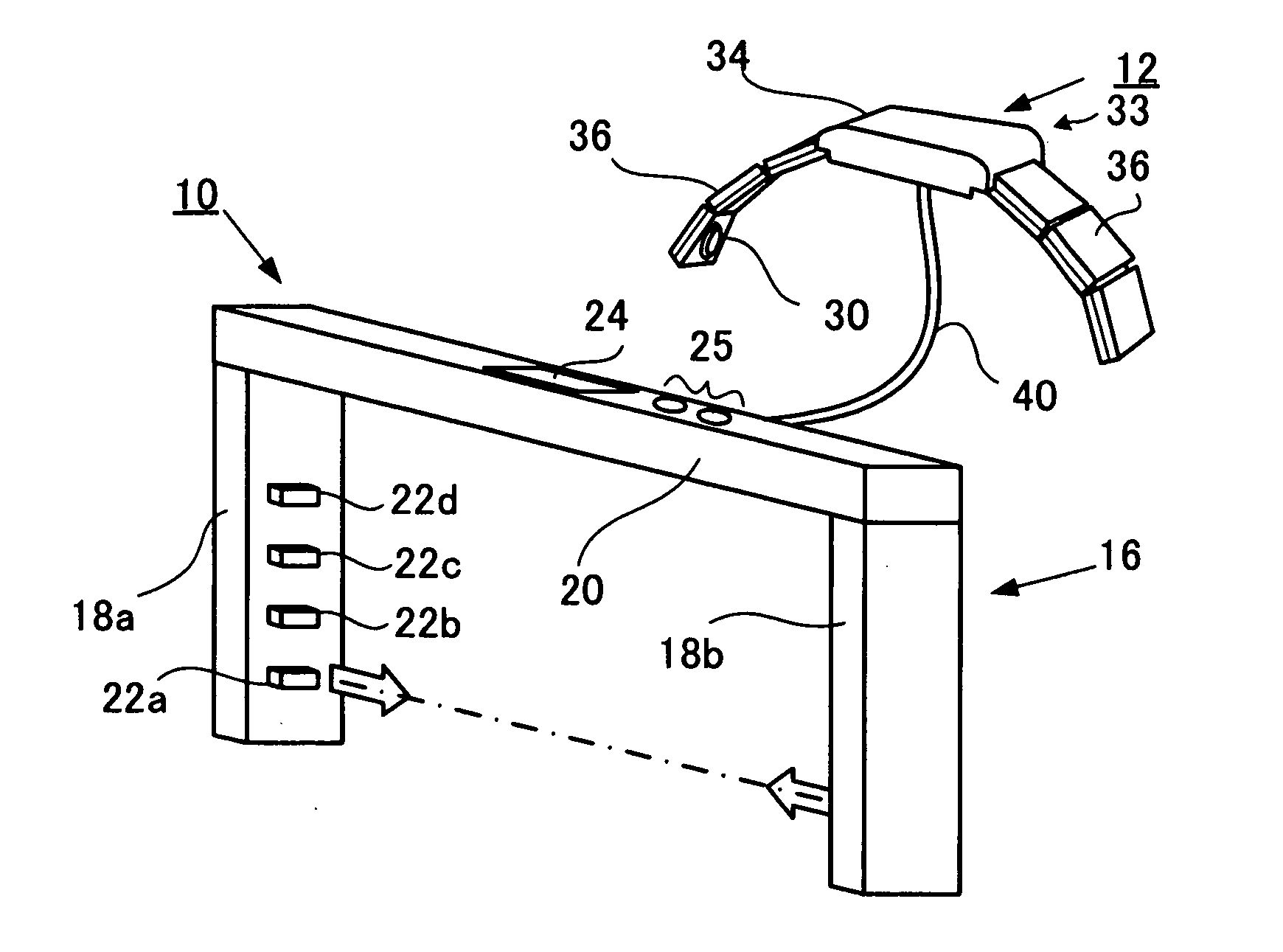
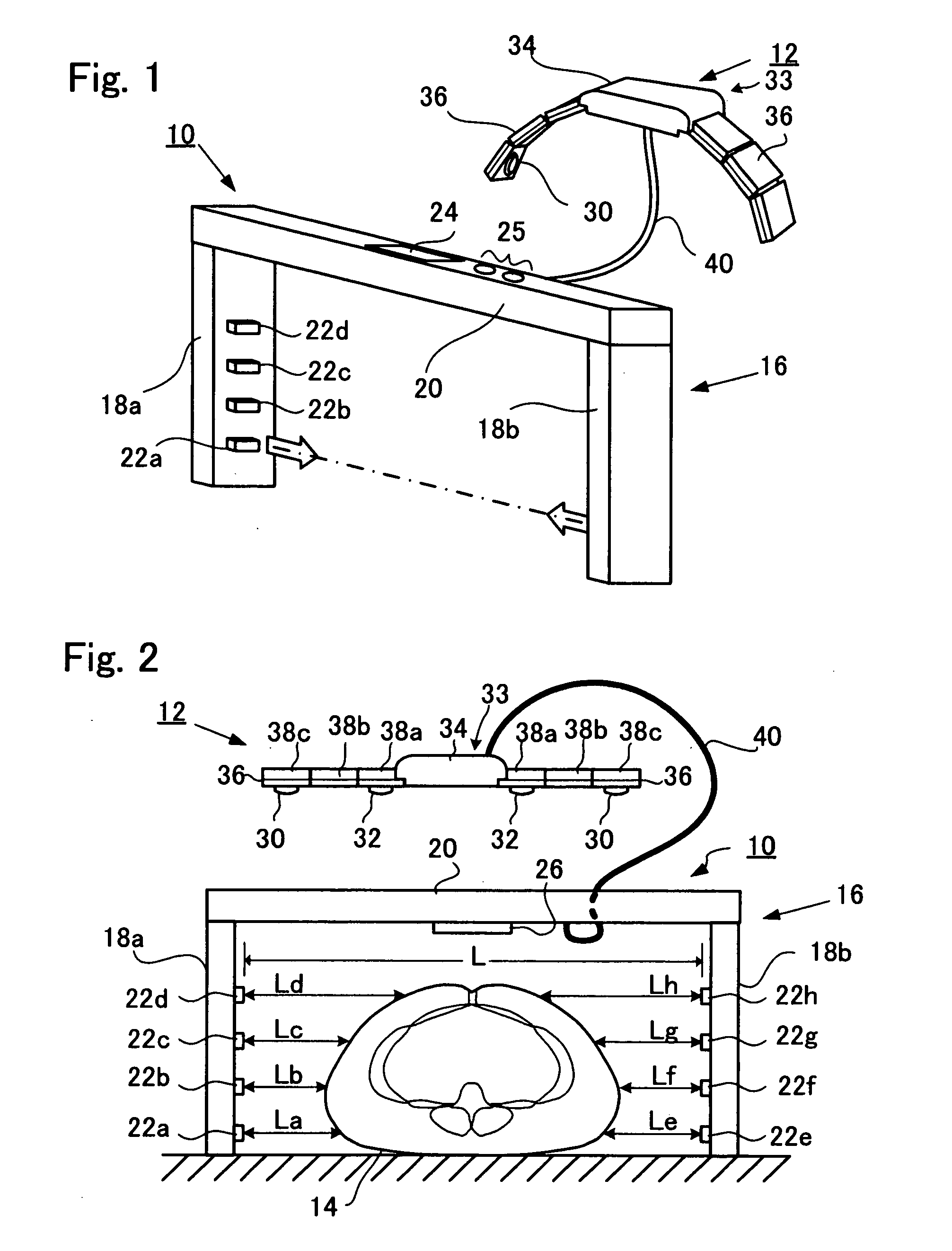
[0029]FIG. 1 is a perspective view of a body composition determination apparatus according to an embodiment of the present invention, and FIG. 2 is a front view of the body composition determination apparatus. The body composition determination apparatus includes an abdominal width determination apparatus 10 and an impedance measuring unit 12. As will be described later, the abdominal impedance measurement apparatus according to the embodiment includes some parts of the abdominal width determination apparatus 10 and the entirety of the impedance-measuring unit 12.

[0030]As shown in FIG. 2, the abdominal width determination apparatus 10 includes a casing (housing), i.e., a frame 16, in the inside of which a human being, i.e., a human subject 14, may be positioned. The frame 16 is...


PUM


Abstract

An abdominal impedance measurement apparatus includes a plurality of electrodes for measuring an abdominal impedance of a human subject, and includes an electrode supporting member for supporting the electrodes in such a manner that the electrodes protrude from the electrode supporting member. The electrode supporting member includes a plurality of segments aligned in a direction, the electrodes being respectively mounted on different segments, neighboring segments being connected rotatably with each other. The electrode supporting member further includes rotation-angle restricting parts for restricting relative rotation-angles between neighboring segments.

Description

BACKGROUND OF THE INVENTION[0001]1. Field of the Invention[0002]The present invention relates to abdominal impedance measurement apparatuses for human bodies.[0003]2. Description of Related Art[0004]In order for accurate measurements to be taken of areas of visceral fat and subcutaneous fat in the bodies of humans, body fat determination apparatuses have been used that calculate body fat data on the basis of tomographic images obtained by various CT (computed tomography) procedures, including X-ray CT and impedance CT, or by MRI (magnetic resonance imaging).[0005]Conventionally, studies have been made in which indexes of body fat were calculated on the basis of impedances measured using impedance measuring electrodes that were brought into contact with the abdomen of a human subject. For example, according to one study, the mass or area of visceral fat of a human body is calculated on the basis of impedance measured using a pair of current-supplying electrodes in contact with the an...

Claims


Application Information

Patent Timeline
Patent Type & Authority Applications(United States)
IPC IPC(8): A61B5/053
CPCA61B5/0537A61B5/1077A61B5/4869A61B5/4872A61B2560/0468
Inventor TSUJI, KOJI
Owner TANITA CORP
Learn More