Variable sized aperture window of an analog-to-digital converter
an analog-to-digital converter and variable-sized aperture technology, applied in analogue/digital conversion, transmission systems, instruments, etc., can solve the problems of not allowing embedding, requiring more expensive chips, and only possible reproduction, and achieve the effect of faster sampling ra
- Summary
- Abstract
- Description
- Claims
- Application Information
AI Technical Summary
Benefits of technology
Problems solved by technology
Method used
Image
Examples
first embodiment
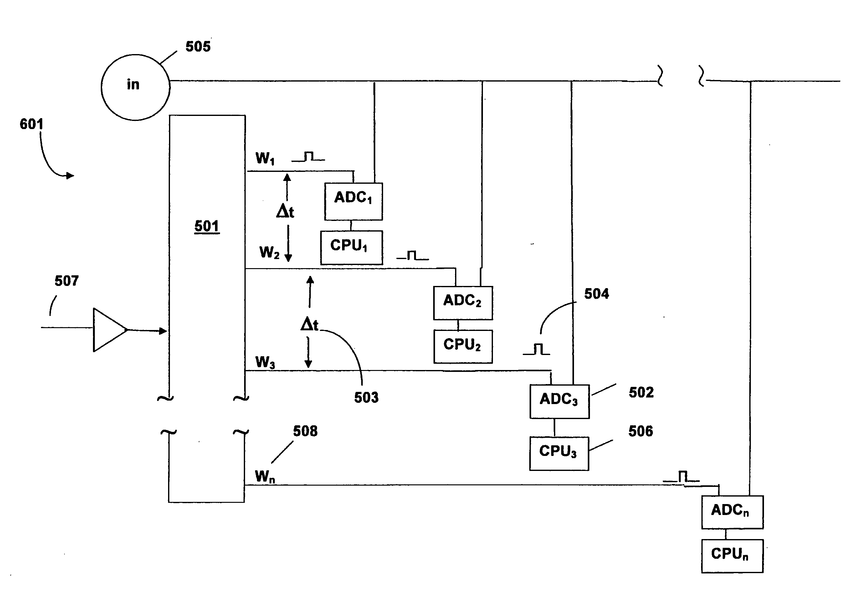
[0049]The time period between each ADC sampling of the input signal could be achieved in various ways, as exemplified by the following embodiments. FIG. 3a discloses a time relationship between samplings taken of an input signal 301 and taps in a trace pattern 303 of a time distributed sampling system in the invention. The trace pattern 303 contains a plurality of elongated wires connected in series. This time distributed sampling system has a plurality of ADC systems, wherein each ADC system comprises an ADC 202 and an associated central processing unit (CPU) 203, as discussed previously in relation to FIG. 2. When a timing signal 306 travels through a first length of wire 303a to a tap point of W1, a prompt to sample the input signal 301 after a measurable amount of time, given by Δt 304 is made. This timing is represented as ADC sampling point C1. As the timing signal 306 continues through a second length of wire 303b to a second tap point of W2, a prompt to sample the input sign...
second embodiment
[0052]FIG. 3b discloses a time relationship between samplings taken of an input signal 301 and taps made in a connected series of inverter pairs 305 of a time distributed sampling system in the invention. Each clocked trace pattern 303 of FIG. 3a is replaced with a pair of inverters 305 in FIG. 3b. A timing signal 306 travels through a series of connected inverter pairs 305. When the timing signal 306 travels through a first inverter pair 305a, a prompt to sample the input signal 301 after a first time period, Δt 304 is made, which coincides with the ADC sampling point C1. As the timing signal 306 continues through a second inverter pair 305b, a prompt to sample the input signal 301 after a second time period, Δt 304 is made, which coincides with the ADC sampling point, C2. A separate ADC system samples the input signal 301 at each of the ADC sampling points, C1 through Cn which occurs when the timing signal 306 travels through each inverter pair at points designated by W1 through W...
third embodiment
[0054]FIG. 4 discloses a time relationship between samplings taken of an input analog signal 405 and line taps made in a specific permittivity material device 401 in the invention. The time distribution sampling is achieved through the use of a specific permittivity material device 401, such as a surface acoustic wave (SAW) device. An input signal 405 is sampled after each measurable time period, Δt 403 as a timing signal 406 travels past each equi-distant point, given by S1 through Sn along the device 401.
[0055]The specific permittivity material device distributed sampling system represented by FIG. 4 works similar to the trace distributed sampling system of FIG. 3a. A separate ADC system contains an ADC and a corresponding CPU, as previously described with reference to FIG. 2. Each sequential ADC system samples the input signal 405, represented by ADC sampling points 402 when a timing signal 406 reaches each sequential equi-distant point along the device 401, corresponding to poin...
PUM
 Abstract
Description
Claims
Application Information
 - R&D Engineer
- R&D Manager
- IP Professional
- Industry Leading Data Capabilities
- Powerful AI technology
- Patent DNA Extraction
Browse by: Latest US Patents, China's latest patents, Technical Efficacy Thesaurus, Application Domain, Technology Topic, Popular Technical Reports.
© 2024 PatSnap. All rights reserved.Legal|Privacy policy|Modern Slavery Act Transparency Statement|Sitemap|About US| Contact US: help@patsnap.com


