Magnetic Bearing Device With an Improved Vacuum Feedthrough

Active Publication Date: 2008-09-25
MECOS
View PDF22 Cites 24 Cited by
  • Summary
  • Abstract
  • Description
  • Claims
  • Application Information

AI Technical Summary

Benefits of technology

[0005]It is therefore an object of the present invention to provide a magnetic bearing device in which a gas-tight electrical connection between the inside and the outside of the housing is established in a simple manner and at a reduced cost.
[0014]Using a flat connection element for the electrical feedthrough simplifies the construction of the feedthrough considerably, reducing the cost of the feedthrough. In the case of a printed circuit board or a flexprint, the substrate provides sealing and insulation of all conductors simultaneously without the need of sealing each conductor individually. A large number of conductors can be carried in the conductive layer or layers of a printed circuit board simultaneously, and the current and voltage rating of the conductors can easily be adapted to the actual requirements by providing broader or thinner traces and larger or smaller gaps between traces in the conductive layer(s). In particular, a custom-designed PCB may be used depending on the actual connections required for each magnetic bearing device in which the feedthrough is to be used. Because of its flat shape, the PCB can be easily sealed to the housing. In addition, a feedthrough according to the present invention requires very little space along the dimension perpendicular to the plane of the connection element.
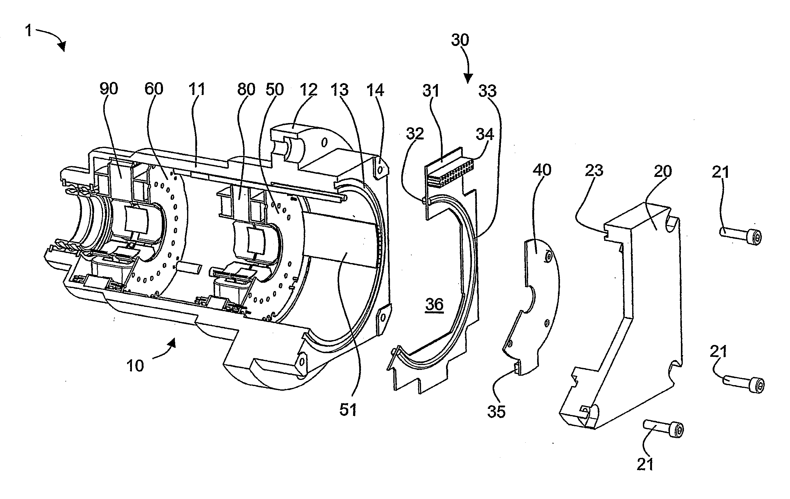
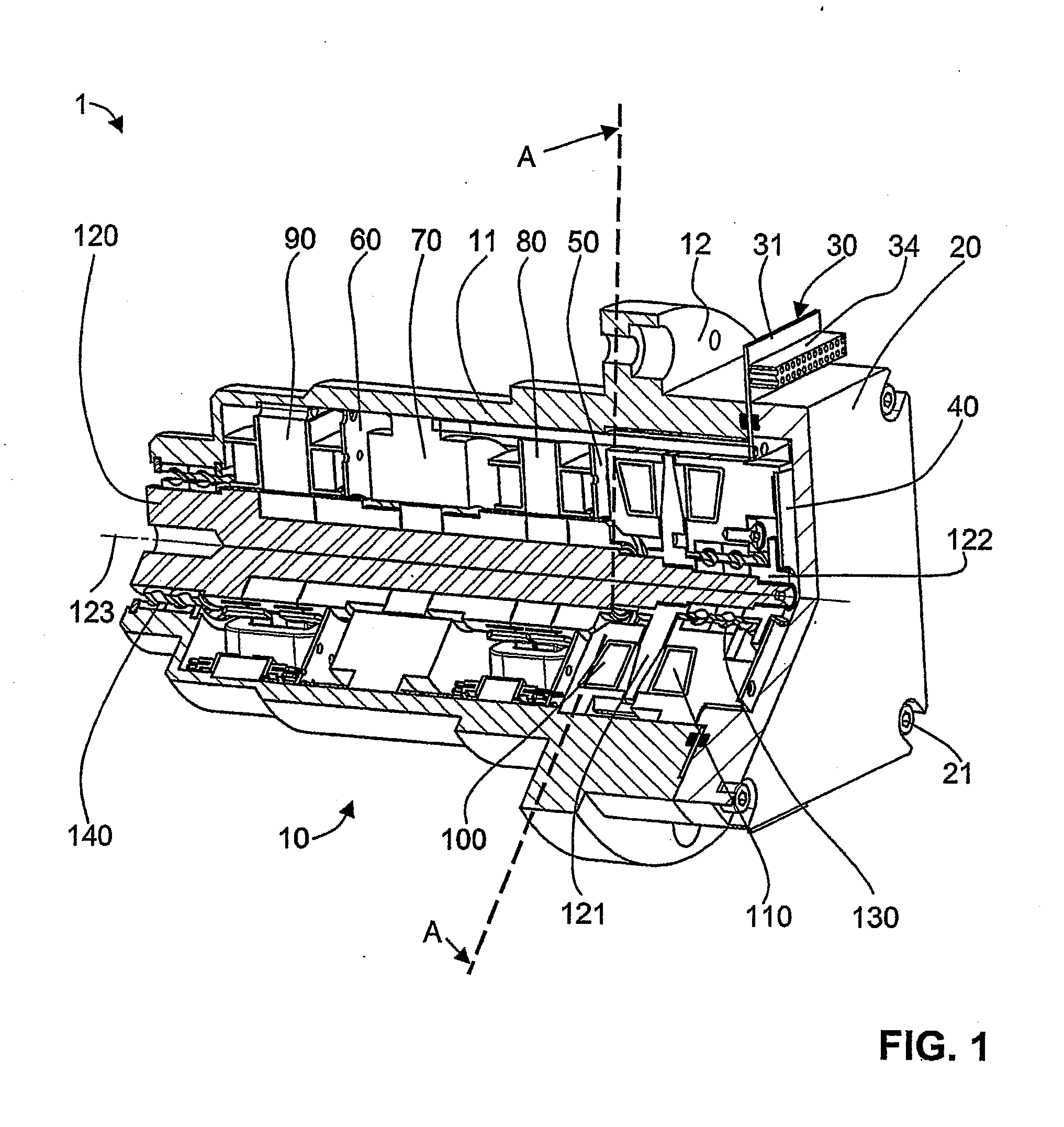
[0016]Preferably, the connection element extends through the housing in a plane essentially perpendicular to the rotation axis. In this case, the connection element preferably has an opening for receiving the rotor shaft. Both measures enable a compact design. Providing a central opening additionally enables a free choice of where the feedthrough may be disposed along the rotor axis. Preferably, the feedthrough is disposed near an axial bearing unit on that side of the unit which points away from the radial bearing units.
[0017]Normally, the rotor shaft will carry a thrust disk. Assembly of the magnetic bearing device is simplified if the opening of the connection element has a diameter larger than the diameter of said thrust disk. In addition, it is preferable that the dimensions of the opening are larger than the lateral dimensions of any axial bearing units. In this way, the axial bearing can be assembled with the feedthrough already in place. Therefore other parts like motors and radial bearing can be assembled and wired to the feedthrough before assembly of rotor and axial bearing.
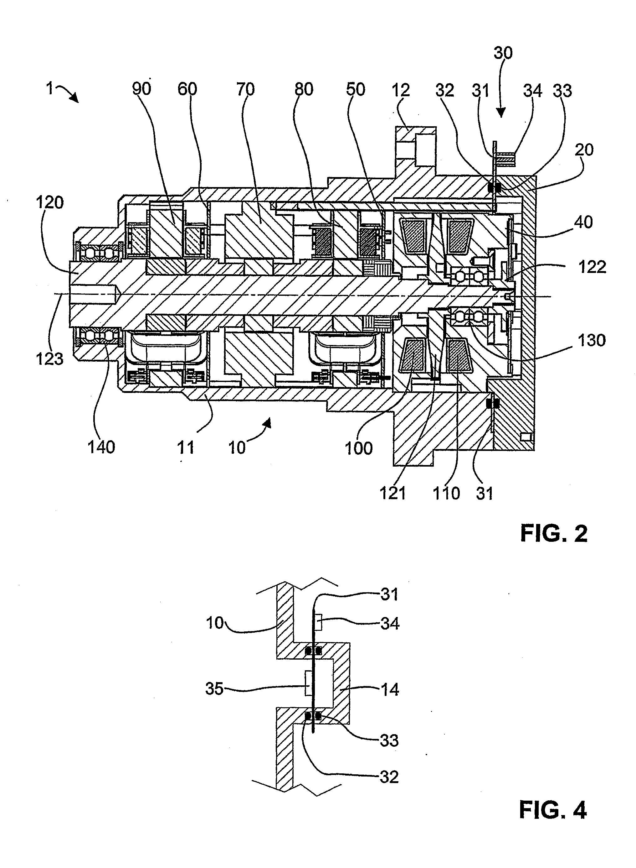
[0019]The sealing means preferably comprise a first O-ring disposed on a first flat side of the connection element. In addition, a second O-ring disposed on a second flat side of the connection element may be present. These O-rings serve to seal the connection element with the housing in a gas-tight manner. The housing may have at least one ring-shaped groove facing the connection element for receiving said first O-ring or said second O-ring. Thereby, the O-rings are received in a well-defined position, and sealing is improved by the presence of the edges of the grooves. Alternatively, one or more flat gaskets may be used. The seals can also be moulded directly to the connection element, in particular, printed circuit board.
[0021]A very simple setup which is easily assembled results if the magnetic bearing device comprises a sensor board with at least one sensor for detecting displacements (in particular, axial displacements) and / or a rotary state of the rotor shaft, said sensor board being directly electrically connected to the feedthrough by means of a connector bridging an axial gap between said feedthrough and said sensor board. The connector is preferably releasable and comprises a socket for receiving a plurality of pins. In this case, no additional cabling is needed for the sensors implemented on the board, and the board can easily be removed in case that servicing of the magnetic bearing device is required. The sensor board may in addition comprise connections for a bearing unit, in particular, an axial (thrust) bearing unit. Said bearing unit (in particular, its coil wires) may be directly connected to the sensor board without further cabling.

Problems solved by technology

Due to the necessity of individually sealing a large number of wires, manufacture of such feedthroughs is relatively expensive, and the cost of the feedthrough may thus contribute significantly to the total cost of the magnetic bearing device.
Additionally, multipin feedthroughs may be rather bulky, which hampers the development of small, low-cost magnetic bearings.
These circuits may, however, be exposed to a hostile environment (vacuum or aggressive gases and high temperatures) within the housing, which decreases the lifespan of the circuits, and the circuits are inaccessible from the outside for servicing, e.g., for an exchange in case of a hardware failure.

Method used


Image

  • Magnetic Bearing Device With an Improved Vacuum Feedthrough
  • Magnetic Bearing Device With an Improved Vacuum Feedthrough
  • Magnetic Bearing Device With an Improved Vacuum Feedthrough

Examples


Embodiment Construction

[0035]FIGS. 1 to 3 show a magnetic bearing device as it is suitable, e.g., for supporting the rotor blades of a turbomolecular pump (TMP). A rotor shaft120 is suspended magnetically in this device for rotation around a rotation axis 123. To this end, a number of magnetic bearing units is provided. A pair of axial or thrust bearing units 100, 110 interact with a thrust disk 121 mounted on the rotor shaft 120 and stabilize the position of the shaft against translational displacements in the axial direction. A first radial bearing unit 80 and a second radial bearing unit 90 stabilize the positions of those shaft portions which are close to these bearing units against radial displacements, thereby achieving stabilization against translational displacements of the shaft in the radial directions and of tilt displacements around the radial directions. A motor unit 70 drives the rotation of the shaft. Auxiliary touch-down bearings implemented as dual ball bearings 130, 140 keep the shaft in...


PUM


Abstract

A magnetic bearing device (1) with an improved vacuum-tight electrical feedthrough through its housing (10) is disclosed. The feedthrough (30) comprises a flat connection element (31) such as a rigid or flexible printed circuit board extending through the wall of the housing (10), preferably all the way along an inner circumference of the housing. The connection element is sealed in a gas-tight manner to the housing. The element preferably has a central opening (36) for receiving the rotor shaft. Connections to the bearing units and sensors may be achieved by flat-ribbon cables (51) or flexprints. The sensors are preferably also implemented as printed sensors. Thus a very compact and cost-efficient magnetic bearing device can be obtained. An alternative embodiment uses a connection element on a side wall of the housing as a feedthrough to the bearing components.

Description

FIELD OF THE INVENTION[0001]The present invention relates to a magnetic bearing device with the features of the preamble of claim 1.BACKGROUND OF THE INVENTION[0002]In the art, magnetic bearing devices are well known in which a rotor is supported for rotation around a rotation axis by a set of active magnetic bearings. These active magnetic bearings are generally arranged within a housing together with a set of displacement sensors. The sensor signals are fed to a controller external to the housing, and depending on these signals, electric currents are provided to the magnetic bearings by the controller. Therefore, an electrical feedthrough for connections between the bearings and sensors within the housing and the controller outside of the housing through a wall of the housing is required. In many applications, such a feedthrough must be sealed in a gastight manner because of the presence of pressure differences between the inside and the outside of the housing. An important applic...

Claims


Application Information

Patent Timeline
IPC IPC(8): F16C32/04H02K7/09
CPCF04D19/048F16C32/0457F16C32/0459F16C32/047F16C2360/44F16C35/00F04D25/0693F16C2360/45F16C32/0489F16C32/0461F04D29/058
Inventor BUHLER, PHILIPPLARSONNEUR, RENE
Owner MECOS
Why Eureka
Try Eureka