
Method of rotating revolver unit using a plurality of motors

a technology of rotating revolvers and motors, applied in the direction of electrographic process apparatus, instruments, optics, etc., can solve the problems of large load torque generated at a part, unstable rotational driving of the developing unit, and the development unit to vibrate and deviate from the stopping position, so as to reduce the load torque generated in the gear when rotating the developing uni

Inactive Publication Date: 2008-09-18
KK TOSHIBA +1
View PDF2 Cites 3 Cited by
  • Summary
  • Abstract
  • Description
  • Claims
  • Application Information

AI Technical Summary

Benefits of technology

The invention reduces the load torque when driving the developing unit in an image forming apparatus, which prevents vibration and unstable rotation of the developing unit. This is achieved by using multiple driving members that rotate the developing unit and move the desired developer to the developing position.

Problems solved by technology

However, when such a heavy developing unit is to be driven by one motor, a large load torque is generated at a part where the developing unit engages with the motor.
This makes the rotational driving of the developing unit unstable, and causes the developing unit to vibrate and deviate from the stopping position.
Moreover, there is a risk of step-out of the motor.
However, in this conventional image forming apparatus, though increase in load torque due to the torque change can be restrained, the original load torque itself generated in the gear of the heavy revolver unit is not reduced.
Therefore, the load torque generated in the gear of the revolver unit is still large and it makes rotational driving of the revolver unit unstable.
There still is a risk of vibration of the revolver unit and occurrence of step-out of the motor.
Also, because of the high-speed rotation of the revolver unit due to the higher speed of the recent color apparatus, the load torque generated in the gear of the revolver unit increase further and it may affect vibration of the revolver unit or step-out of the motor.

Method used


Image

  • Method of rotating revolver unit using a plurality of motors
  • Method of rotating revolver unit using a plurality of motors
  • Method of rotating revolver unit using a plurality of motors

Examples


first embodiment

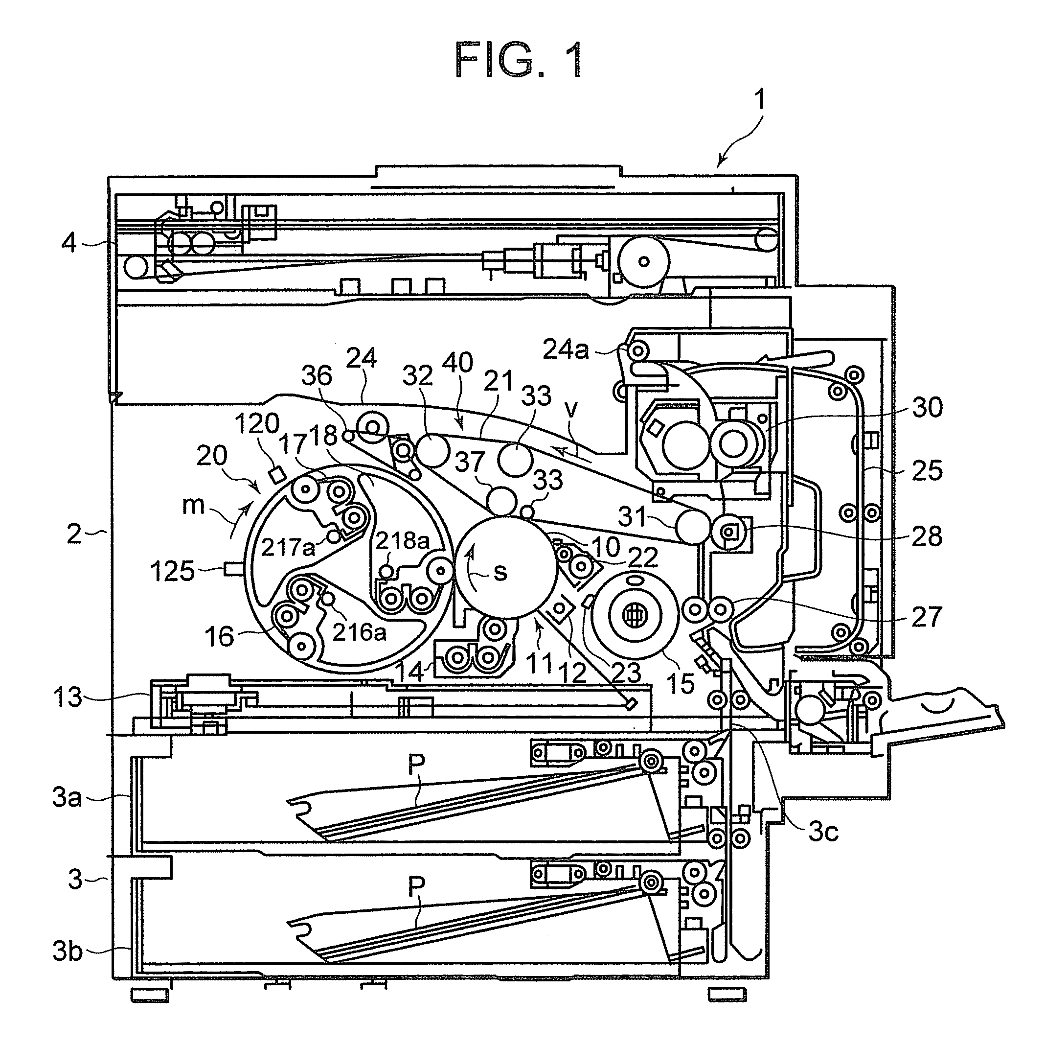
[0019]Hereinafter, an embodiment of the invention will be described in detail with reference to the accompanying drawings. FIG. 1 is a schematic configuration view showing a color printer 1, which is an image forming apparatus according to the invention. The color printer 1 has a printer unit 2, a paper feed unit 3 which supplies a sheet paper P to the printer unit 2, and a scanner unit 4 which reads an original image.

[0020]A toner image forming unit 11, which is an image forming member to form toner images of a plurality of colors on the photoconductive drum 10, is provided around a photoconductive drum 10 of the printer unit 2. The toner image forming unit 11 has a charger device 12 which uniformly charges the photoconductive drum 10, a laser exposure device 13 which forms an electrostatic latent image on the charged photoconductive drum 10 on the basis of image data from the scanner unit 4, and a black developing device 14 which is supplied with toner from a black toner cartridge...

second embodiment

[0065]In the second embodiment, at the time of any of detection of the home position of the revolver unit 20, toner supply, and development, the main and auxiliary stepping motors 127 and 128 are simultaneously operated to rotationally drive the revolver unit 20.

[0066]According to the second embodiment, since the revolver unit 20 is rotationally driven by the main and auxiliary stepping motors 127 and 128, the load torque in the parts where the follower gear 20b engages with the driving shafts 127a and 128a can be reduced, compared with the conventional case of driving it by a single stepping motor. Thus, as in the above first embodiment, reduction in size and price of each stepping motor can be realized and consumption energy can be saved. Moreover, durability of the follower gear 20b can be improved. As a result, it is possible to easily deal with demands for higher-speed operation of the color printer 1.

[0067]In the second embodiment, the main stepping motor and the auxiliary ste...


PUM


Abstract

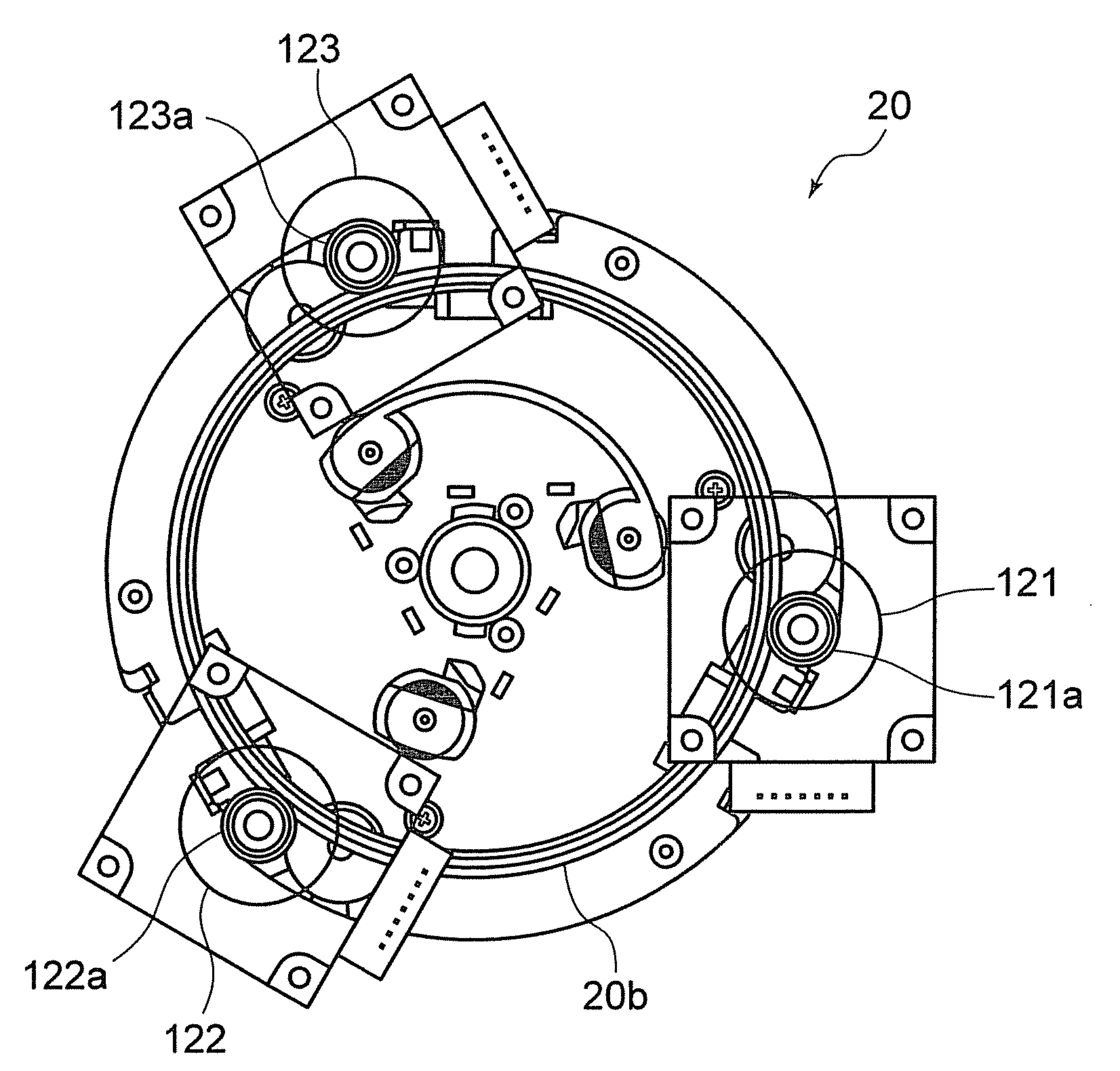
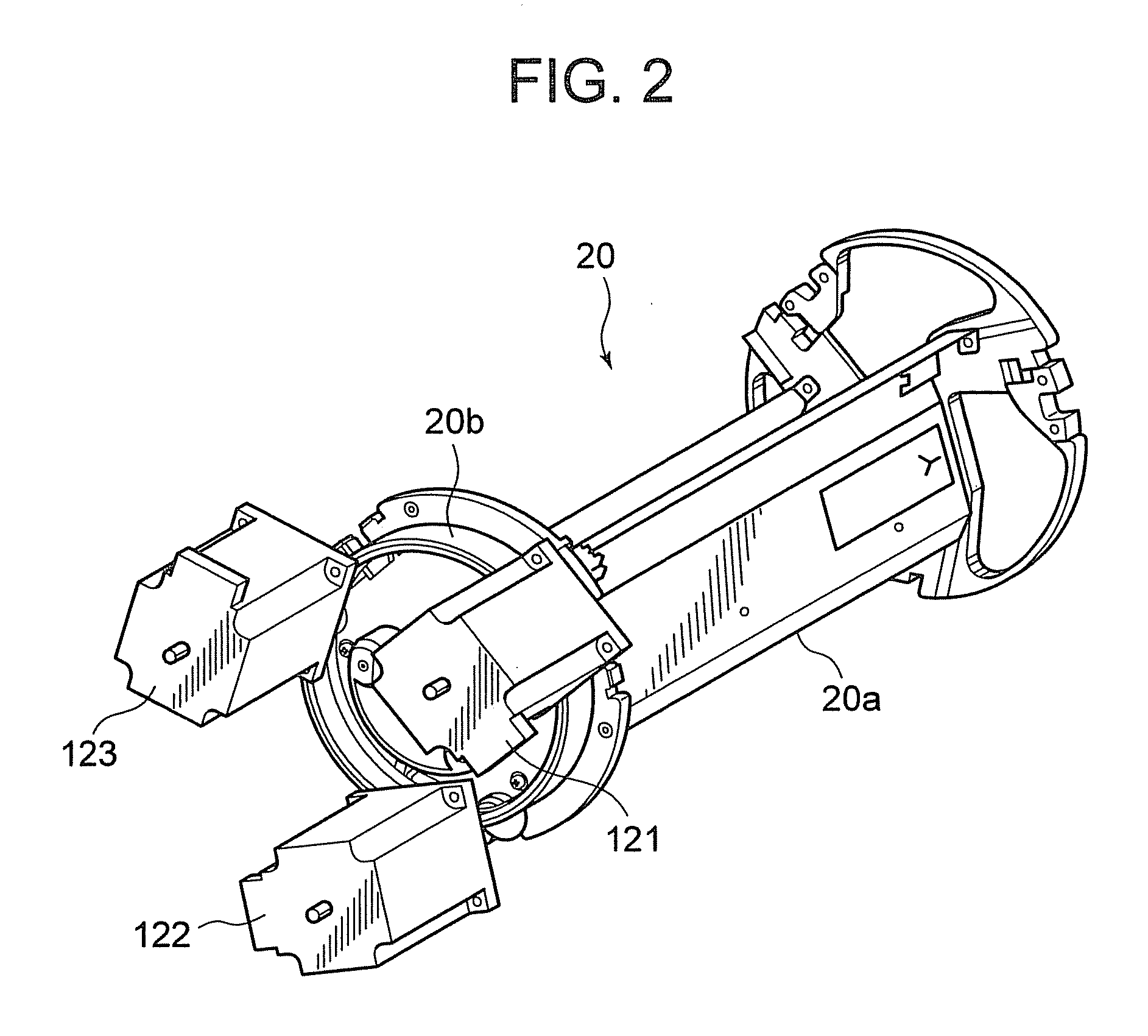
According to an embodiment of the invention, a revolver unit is rotationally driven by using three stepping motors. The weight of developing cartridges loaded on the revolver unit is identified on the basis of the quantity of remaining toner in toner cartridges. At the time of rotationally driving the revolver unit, output timing of the stepping motor closer to the developing cartridge which has a large quantity of remaining toner and has a heavy weight is made earlier, and output timing of the stepping motor far from this developing cartridge is delayed.

Description

CROSS REFERENCE TO RELATED APPLICATION[0001]This invention is based upon and claims the benefit of priority from prior U.S. Patent Application 60 / 895,366 filed on Mar. 16, 2007, the entire contents of which are incorporated herein by reference.BACKGROUND OF THE INVENTION[0002]1. Field of the Invention[0003]The present invention relates to an image forming apparatus such as an electrophotographic apparatus, a printer or the like and to an image forming apparatus having a developing unit which is equipped with developers for plurality of colors and provided rotatably.[0004]2. Description of the Related Art[0005]As an image forming apparatus such as a color copy machine, a color printer or the like which provides color images by an electrophotographic system, there is an apparatus having a revolver-type developing device in which a developing unit having an integrated developing device and toner cartridge and equipped with a plurality of developers is rotated to move a developer of a d...

Claims


Application Information

Patent Timeline
Patent Type & Authority Applications(United States)
IPC IPC(8): G03G15/08
CPCG03G2215/0177G03G15/0126
Inventor OGIWARA, TAKASHI
Owner KK TOSHIBA
Learn More