
System and method for normalization and calibration of an imaging system using a variable thickness filter

Active Publication Date: 2008-09-18
LEIDOS
View PDF4 Cites 1 Cited by
  • Summary
  • Abstract
  • Description
  • Claims
  • Application Information

AI Technical Summary

Benefits of technology

[0005]In the NII and NDT art, the ultimate goal is to produce high quality images of the interior/contents of a target. It is known in the art to transmit a collimated electromagnetic radiation beam, e.g., x-ray or gamma, from a radiation source towards the target and collect the transmitted radiation after it has passed through the target at a detector array. The detected radiation can be used to infer line of sight density information about the target and its contents. Relative motion between the system and target is used to provide a multi-dimensional image. In order to produce an image which accurately represents the target's internal density distribution, it is necessary to calibrate the response of the detector array to the range of densities which may occur in the target and it

Problems solved by technology

The prior art presents a problem since the solid, steel block represents an extra component that must be included with the radiation source configuration.
This component adds weight to the configuration and increases the size thereof, thus requiring additional shielding around the source configuration and further encroaching into the imaging lane where even a single foot is significant at, e.g., ports and border crossings, which utilize multiple traffic imaging lanes.
The prior art step wedge offers no flexibility.

Method used


Image

  • System and method for normalization and calibration of an imaging system using a variable thickness filter
  • System and method for normalization and calibration of an imaging system using a variable thickness filter
  • System and method for normalization and calibration of an imaging system using a variable thickness filter

Examples


Embodiment Construction

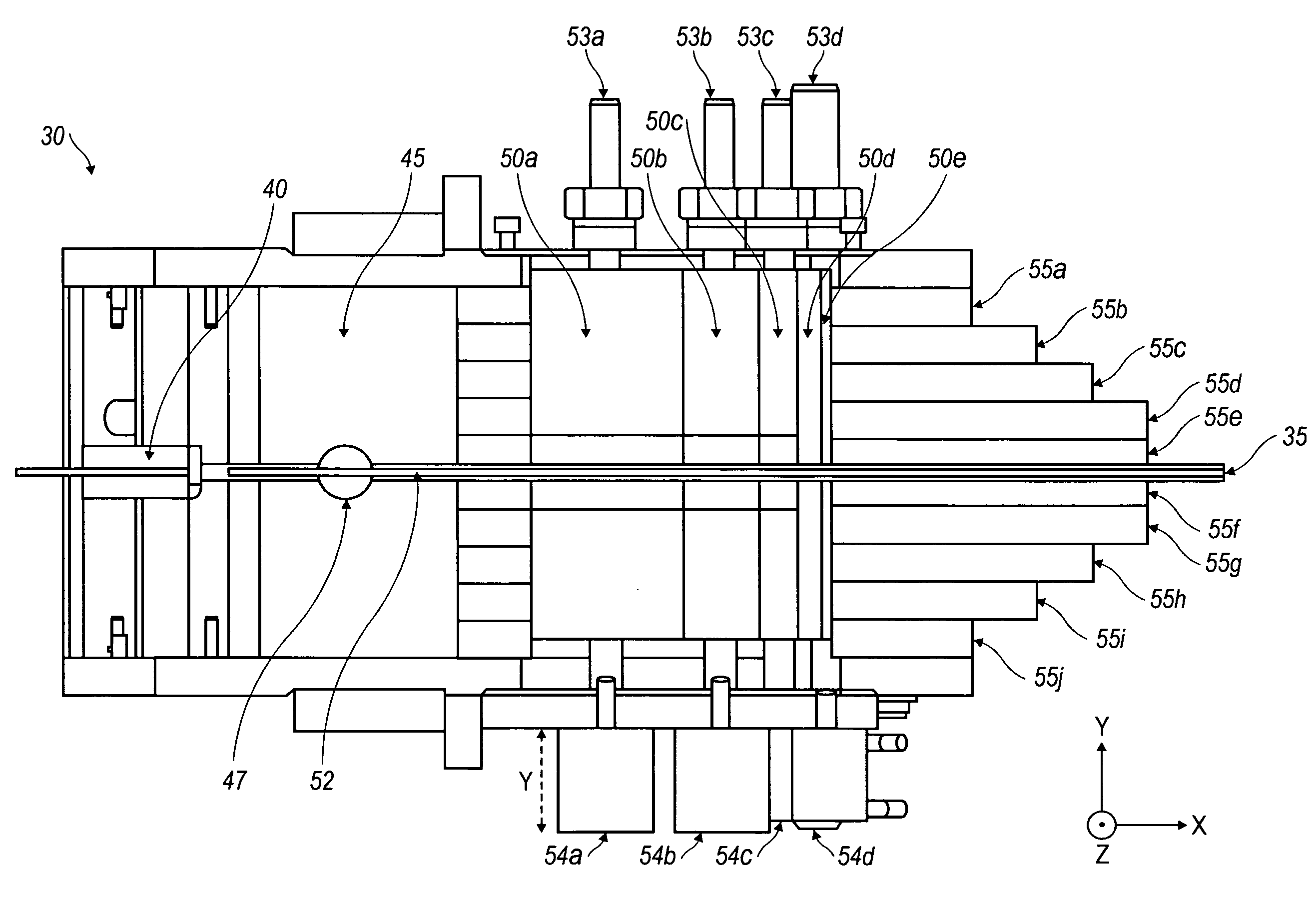
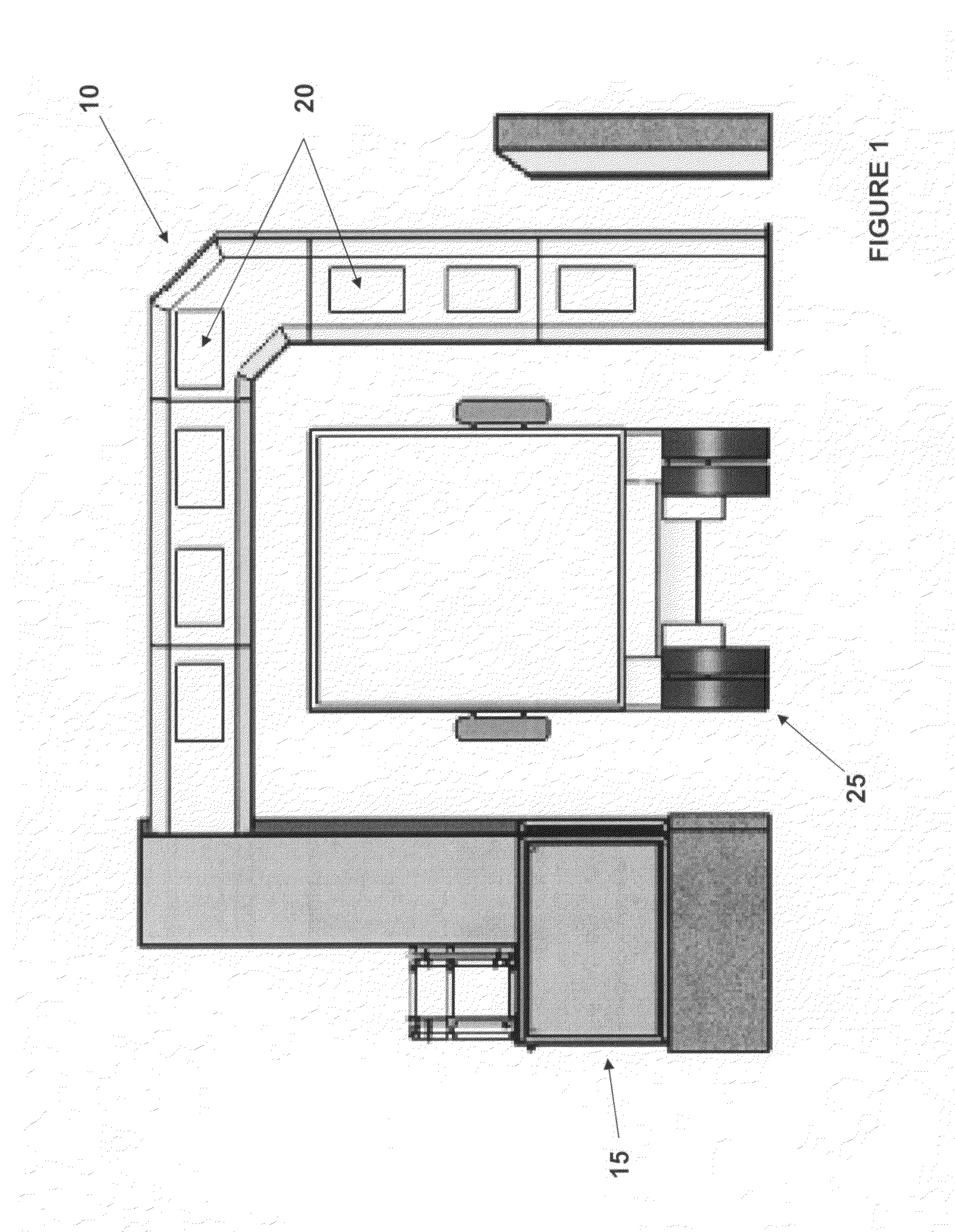
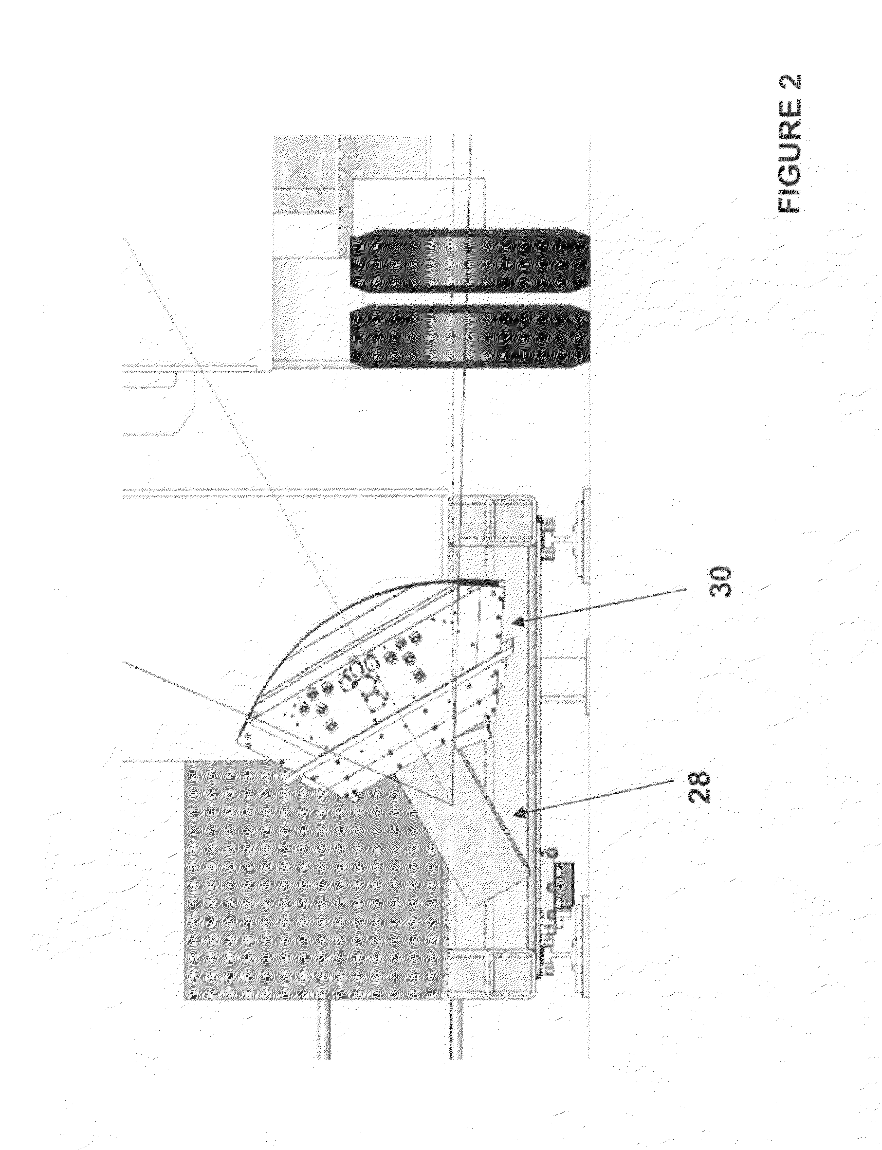
[0016]The present invention is best described in the context of a larger device invention 10 for imaging the contents of a target, e.g., vehicle, shown in FIG. 1. The exemplary device 10 includes, among other components, a source assembly 15 and at least one detector 20 for measuring the intensity of radiation transmitted through the target 25. The source assembly 15 emits penetrating electromagnetic radiation, e.g., x-ray or gamma radiation. Included in source assembly 15 is a collimator subassembly 30 as shown in FIG. 2. The collimator subassembly 30 acts on x-ray or gamma radiation emitted from source 28. For example, in a particular embodiment, x-rays are generated by a betatron. Generally, the x-rays generated by the betatron result in a broad, cylindrically symmetric beam. The device 10 requires a narrow, fan-shaped beam of x-rays. Accordingly, the system utilizes a collimator, usually in the form of a slit, that shapes the beam. The slit is located in front of the x-ray sourc...


PUM


Abstract

A system and method for calibrating a radiation imaging system include a dual use variable thickness radiation filter having a slit in one part thereof such that in a first position a radiation beam passing through is not attenuated and in a second position the radiation beam is attenuated according to the total filter thickness in the path of the radiation beam. The filter may be formed of multiple movable plates or a single piece of stepped high density material.

Description

BACKGROUND OF THE INVENTION[0001]1. Field of the Invention[0002]The invention relates generally to the fields of cargo screening, non-intrusive inspection (NII), non-destructive testing (NDT), and, more particularly, to systems and methods for calibrating such devices.[0003]2. Description of the Related Art[0004]Most currently available normalization filters for use with high energy imaging systems are referred to as “step wedge” devices. A step wedge is a single block of material which is cut into steps. Each step is a different thickness that may be placed into the radiation beam. To have many thicknesses one must have many steps. Since each step is in series the wedge is driven with a positioning system which can place each step in the beam. This requires a motion control capability. The step wedge does not perform any of the collimation functions necessary for operation of an imaging system and thus represents yet another component to the source assembly which adds bulk, weight ...

Claims


Application Information

Patent Timeline
IPC IPC(8): G01D18/00
CPCG01T7/005
Inventor HORSTMAN, STEVEN JONFRIES, WILLIAM M.HEINDL, WILLIAM ADAMS
Owner LEIDOS
Learn More