
Aerodynamic lifting device and airborne craft

Active Publication Date: 2008-09-18
ENTECHO (PTY) LTD
View PDF21 Cites 12 Cited by
  • Summary
  • Abstract
  • Description
  • Claims
  • Application Information

AI Technical Summary

Benefits of technology

[0005]One important limitation of such craft is the inability to operate over terrain with obstacles of significant size such as waves, boulders, riverbanks and the like because close contact must be made with the ground to avoid the leakage of the air cushion. Any increase in the operating height of the hovercraft is accompanied by an unrealistic horsepower requirement. A further notable limitation is the inability to develop significant lateral thrust for acceleration, braking, climbing gradients and changing direction with realistic horsepower requirements despite the use of separate fans for developing this lateral thrust. In general, the “footprint” of the hovercraft is acceptably small for its lifting capacity because the entire area under the craft and an appropriate peripheral skirt encapsulates an air cushion which can operate at sufficient pressure with low power requirements provided that the clearance between the grounds and the skirt is small so as to minimize air leakage. In effect the air cushion of a hovercraft provides a low friction sliding surface over which the hovercraft may move.
[0079]A particular advantage of the aerodynamic lifting device and airborne craft of the present invention is the lesser noise compared to helicopters and other similar craft.

Problems solved by technology

This craft has a number of disadvantages that have limited its penetration of markets for motorized recreational products and general transportation of personnel and goods.
One important limitation of such craft is the inability to operate over terrain with obstacles of significant size such as waves, boulders, riverbanks and the like because close contact must be made with the ground to avoid the leakage of the air cushion.
Any increase in the operating height of the hovercraft is accompanied by an unrealistic horsepower requirement.
A further notable limitation is the inability to develop significant lateral thrust for acceleration, braking, climbing gradients and changing direction with realistic horsepower requirements despite the use of separate fans for developing this lateral thrust.
The main undesirable characteristic of helicopters is the long rotating blades, which are a hazard to personnel and to the aircraft itself should they strike anything in the area and the very large footprint or minimum safe space requirements that these aircraft require, particularly during takeoff and landing.

Method used


Image

  • Aerodynamic lifting device and airborne craft
  • Aerodynamic lifting device and airborne craft
  • Aerodynamic lifting device and airborne craft

Examples


Embodiment Construction

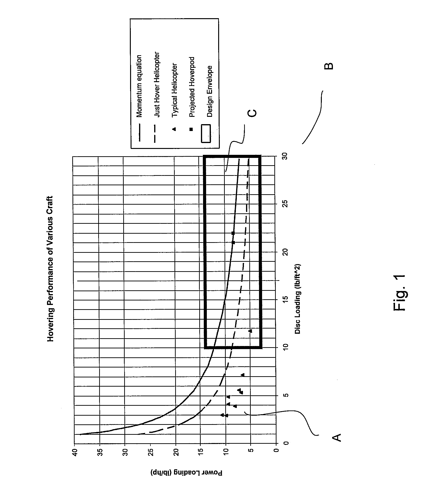
[0093]Referring to FIG. 1 there is shown a power loading (“y”)-disc loading (“x”) characteristic conventionally used in the field of helicopter design and showing operating points for helicopters using long rotating blades in accordance with current practice. These points assist in defining an operating region for current hovering craft which corresponds to a region in which power loading asymptotes and which may be described as the power loading or y asymptotic region “A”. Intermediate this region and the disc loading or x asymptotic region, “B”, lies an intermediate region “C” forming the design envelope for airborne hovering craft forming one aspect of this invention. The intermediate region “C” may also be defined, by way of more specific example, as an operating region in which an aerodynamic lifting device or airborne craft (referred to as a “Hoverpod” aircraft) has a band of disc loadings or weight per unit of lift area from 10 to 30 lb / sq ft as shown on the horizontal, or “X...


PUM


Abstract

An airborne craft is provided comprising an aerodynamic lifting device having a radial drum fan and a thrust vectoring shroud. The radial drum or vertical axis fan comprises a fan with a rotor, the rotor having a rotational axis and comprising a plurality of rotor blades disposed in an annular ring about the rotational axis and a driving means for the rotor such that, on operation of the driving means, lift is generated.

Description

[0001]This application is a Continuation-In-Part of pending U.S. patent application Ser. No. 11 / 377,098, filed Mar. 15, 2006, which claims the benefit of Australian Patent Application Nos. 2005901244, 2005901245 and 2005901246, each filed Mar. 15, 2005, and a Continuation-In-Part of pending PCT application Serial No. PCT / AU2007 / 001718, filed Nov. 9, 2007, the entire disclosures of which are incorporated by reference herein.FIELD OF THE INVENTION[0002]This invention relates to aerodynamic lifting devices for airborne craft.BACKGROUND / SUMMARY OF THE INVENTION[0003]Powered airborne craft, manned and unmanned, may be capable of hovering in a stationary position while airborne. Such aircraft may range from craft which operate close to the ground relying on a cushion of air to those capable of free flight and vertical takeoff and landing. Craft operating close to the ground may be designed for transportation and recreational use whereas the free flight craft may operate at generally low a...

Claims


Application Information

Patent Timeline
IPC IPC(8): B64C29/00B64C39/06
CPCB64C39/064
Inventor SCHLUNKE, CHRISTOPHER KIM
Owner ENTECHO (PTY) LTD
Learn More