Wet type friction plate

a friction plate and wet technology, applied in the direction of friction lining, mechanical actuated clutch, mechanical apparatus, etc., can solve the problems of increased number of grooves to be formed in the friction plate, poor heat resistance, and poor heat resistance, and achieve excellent heat resistance and effective lubrication of the friction engagement surfa

Inactive Publication Date: 2008-09-18
NSK WARNER
View PDF4 Cites 1 Cited by
  • Summary
  • Abstract
  • Description
  • Claims
  • Application Information

AI Technical Summary

Benefits of technology

[0013]Accordingly, an object of the present invention is to provide a wet type friction plate which can lubricate a friction engagement surface effectively even with a small amount of supplied oil and which has excellent heat-resistance.
[0015]According to the present invention, the following advantages can be obtained.
[0016]Since the width of the groove configuration is increased from the inner and outer diameter portions of the friction surface to the intermediate portion in the arc fashion, as the number of rotations or revolutions is increased, negative pressure is generated in the groove thereby to take in lubricating oil from the inner diameter portion or the outer diameter portion into the groove, and the taken-in lubricating oil is supplied from the groove to the friction surface effectively, thereby efficiently eliminating friction heat generated upon the engagement of the clutch.
[0017]Further, in association with a lubricating path, by increasing a width of an opening portion of the inner diameter portion more than a width of an opening portion of the outer diameter portion in a case where an amount of the lubricating oil taken in from the inner diameter portion is desired to be increased, and, by increasing the width of the opening portion of the outer diameter portion more than the width of the opening portion of the inner diameter portion in a case where an amount of the lubricating oil taken in from the outer diameter portion is desired to be increased, the friction surface can be lubricated more effectively.
[0018]Further, by designing the groove to be inclined with respect to a rotational direction of the wet type friction plate, the effect can be more increased.

Problems solved by technology

Although the oil from the oil groove extending through from the inner periphery to the outer periphery in the radial direction is used to supply the oil to the friction surface and to discharge the oil, the flow of the oil from the oil groove to the friction surface is greatly influenced by a configuration of the oil groove and the like, with the result that the oil flow affects an influence upon the idle rotation torque and the friction property during the engagement, thereby causing dispersion in plate quality.
To this end, the increase in the number of grooves to be formed in the friction plate and the size of the groove has been limited or restricted severely.
In the conventional straight configuration of the groove as disclosed in the above-mentioned Japanese Patent Application Laid-open Nos. 11-141570 (1999) and 2005-76759, the groove could not provide a sufficient negative pressure effect to take in the lubricating oil.
Further, the lubricating oil in the groove was hard to be supplied to the friction surface efficiently, and a great amount of the lubricating oil was discharged from the groove to the outside without passing through the friction surface.

Method used


Image

  • Wet type friction plate
  • Wet type friction plate
  • Wet type friction plate

Examples


first embodiment

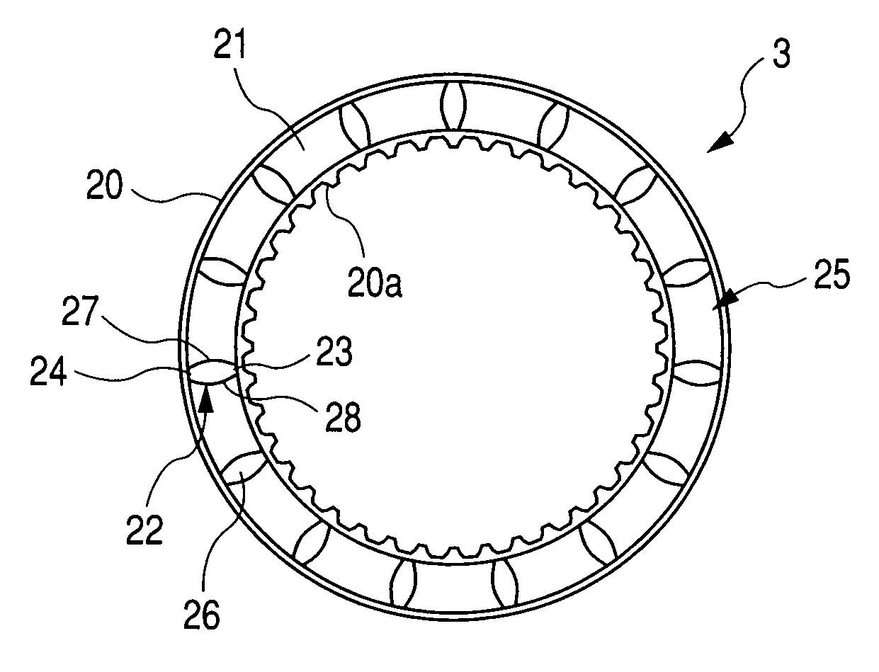
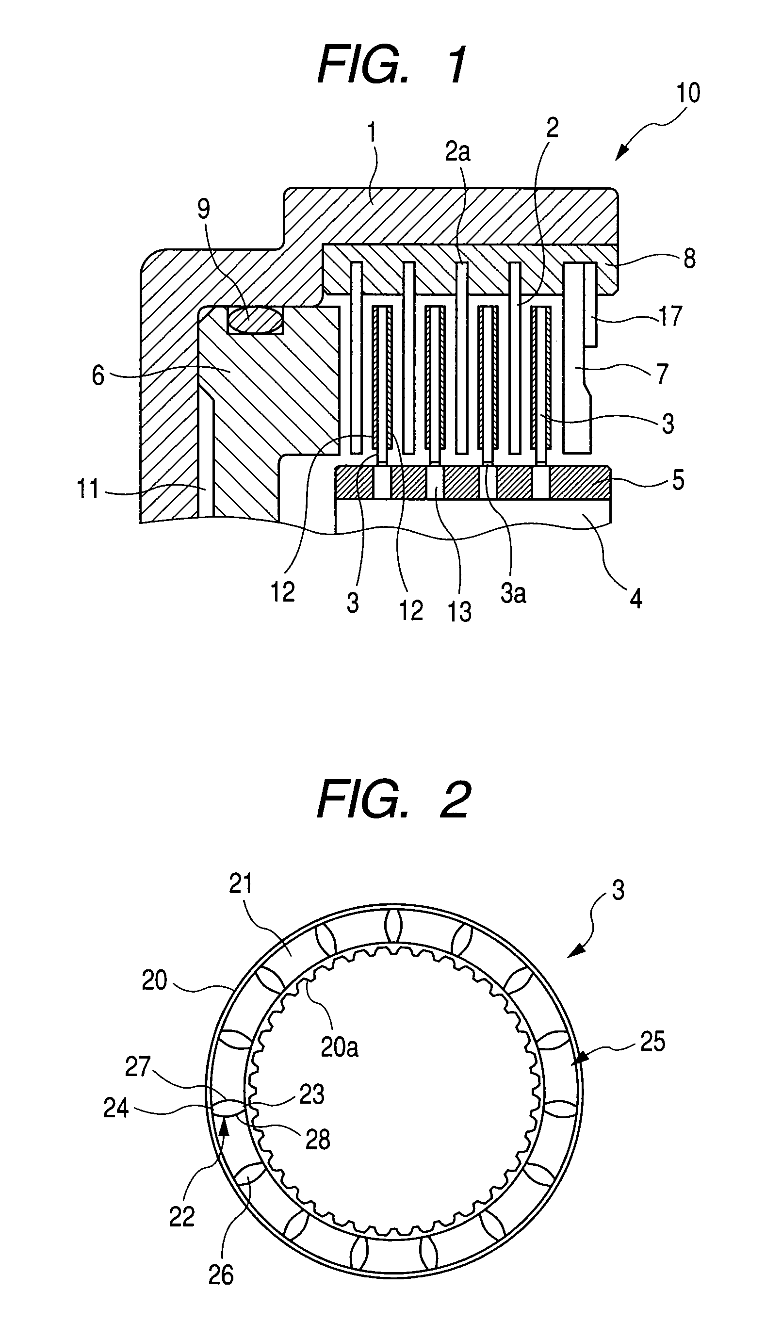
[0037]FIG. 2 is a front view of a wet type friction plate according to a first embodiment of the present invention. The wet type friction plate 3 has a friction surface 25 formed by sticking or fixing a substantially annular friction material 21 to a substantially annular core plate 20 by an adhesive or the like. The core plate 20 is provided at its inner periphery with splines 20a adapted to be engaged by the spline portion 5 of the hub 4.

[0038]As shown, a plurality of grooves 22 equidistantly spaced apart from each other along a circumferential direction is formed in the friction material 21 by a press or the like. The groove 22 is defined between two opposed sides 27 and 28 of the friction material 21. The groove 22 is provided with a radial intermediate portion 26 having a width greater than widths of opening portions 23 and 24 formed at inner and outer diameter portions, respectively. The circumferential width of the opening portion 23 is the same as that of the opening portion...

second embodiment

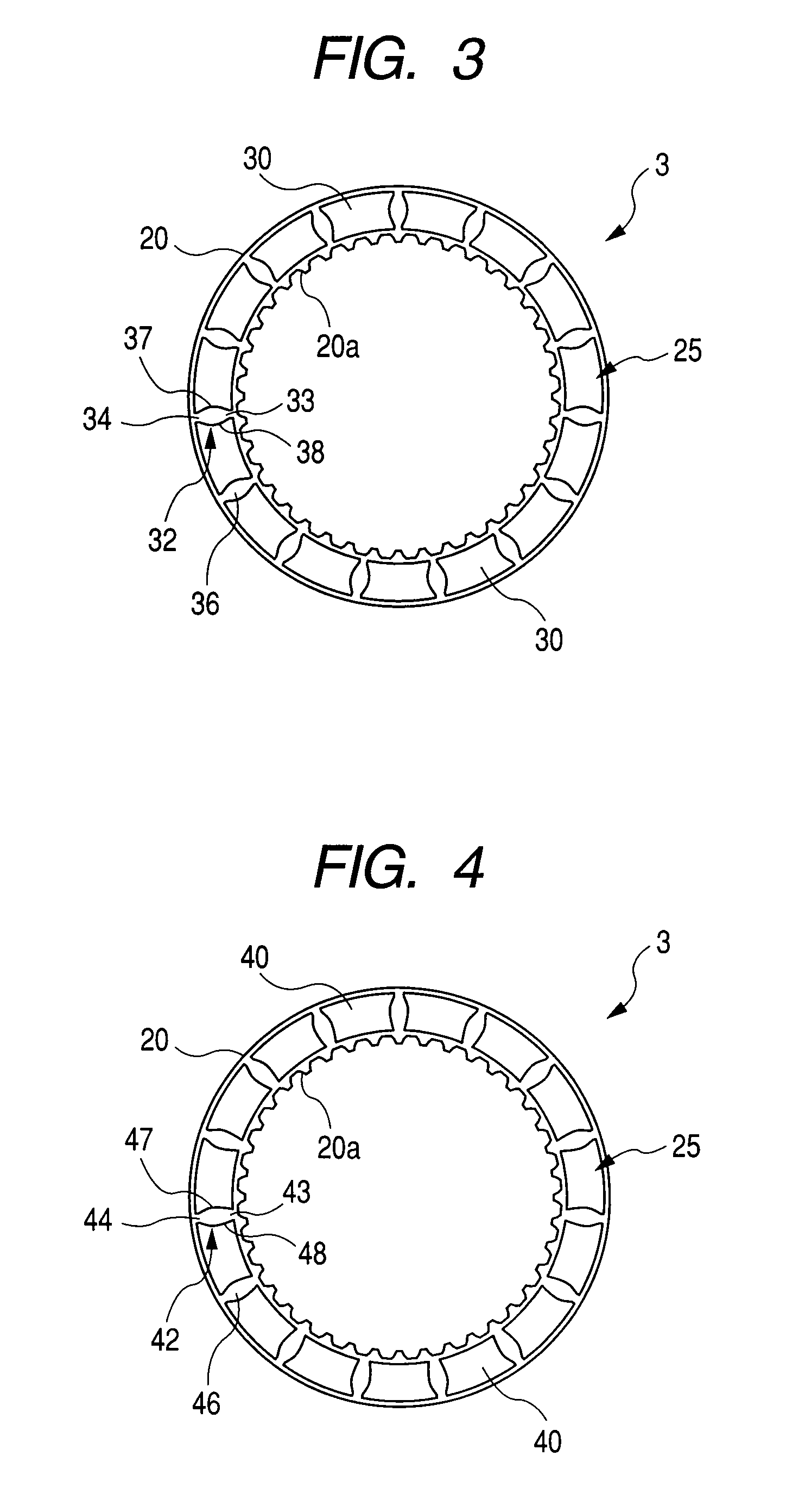
[0040]FIG. 3 is a front view of a wet type friction plate according to a second embodiment of the present invention. Unlike to the first embodiment, the friction material is constituted by discrete friction material segments. The wet type friction plate 3 has a friction surface 25 formed by fixing a plurality of friction material segments 30 having the same configuration to a substantially annular core plate 20 in an annular arrangement by an adhesive or the like.

[0041]As shown, a plurality of grooves 32 equidistantly spaced apart from each other along a circumferential direction is formed between the friction material segments 30. The groove 32 is defined between two opposed sides 37 and 38 of the friction material segments 30. The groove 32 is provided with a radial intermediate portion 36 having a width greater than widths of opening portions 33 and 34 formed at inner and outer diameter portions, respectively. The circumferential width of the opening portion 33 is the same as tha...

third embodiment

[0043]FIG. 4 is a front view of a wet type friction plate according to a third embodiment of the present invention. Similar to the second embodiment, the friction material is constituted by discrete friction material segments. The wet type friction plate 3 has a friction surface 25 formed by fixing a plurality of friction material segments 40 having the same configuration to a substantially annular core plate 20 in an annular arrangement by an adhesive or the like.

[0044]As shown, a plurality of grooves 42 equidistantly spaced apart from each other along a circumferential direction is formed between the friction material segments 40. The groove 42 is defined between two opposed sides 47 and 48 of the friction material segments 40. The groove 42 is provided with a radial intermediate portion 46 having a width greater than widths of opening portions 43 and 44 formed at inner and outer diameter portions, respectively.

[0045]Unlike to the first and second embodiments, in the third embodim...


PUM


Abstract

The present invention provides a wet type friction plate having a friction surface formed by fixing a friction material to a substantially annular core plate in an annular arrangement, in which a plurality of grooves extending through from an inner diameter portion to an outer diameter portion is formed in the friction surface and at least one of both side portions of the friction material defining the groove is formed as an arc configuration and the groove has a radial intermediate portion having a width greater than those of the inner diameter portion and the outer diameter portion.

Description

BACKGROUND OF THE INVENTION[0001]1. Field of the Invention[0002]The present invention relates to a wet type friction plate used in a speed change clutch, a lock-up clutch for a torque converter, a wet type multi-plate clutch for a starting clutch and the like utilized in a clutch or a brake and the like of an automatic transmission (AT) of a vehicle.[0003]2. Description of the Related Art[0004]In general, in a wet type multi-plate clutch, friction plates and separator plates are disposed alternately between a drum and a hub of a clutch or a brake so that the clutch is engaged and disengaged by applying to and releasing from a force with respect to the plates by means of a clutch piston, respectively.[0005]Further, in recent years, low fuel consumption of a motor vehicle has been requested more and more, and, also in an automatic transmission, reduction in drag torque between the friction plate and the separator plate has been requested more and more in order to reduce power loss dur...

Claims


Application Information

Patent Timeline
IPC IPC(8): F16D13/64
CPCF16D25/123F16D2065/1312F16D69/0408F16D69/00
Inventor KINPARA, HIROYUKI
Owner NSK WARNER
Why Eureka
Try Eureka