Startup Torque Transmitting Mechanism of an Internal Combustion Engine
a technology of starting torque and transmitting mechanism, which is applied in the direction of engine starters, machines/engines, power operated starters, etc., can solve the problems of impact noise produced, achieve the effect of preventing the deformation of the race connecting member, easy deformation, and increase load
- Summary
- Abstract
- Description
- Claims
- Application Information
AI Technical Summary
Benefits of technology
Problems solved by technology
Method used
Image

Examples
first embodiment
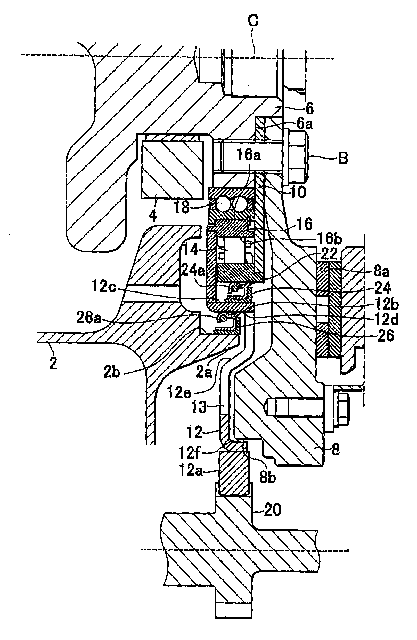
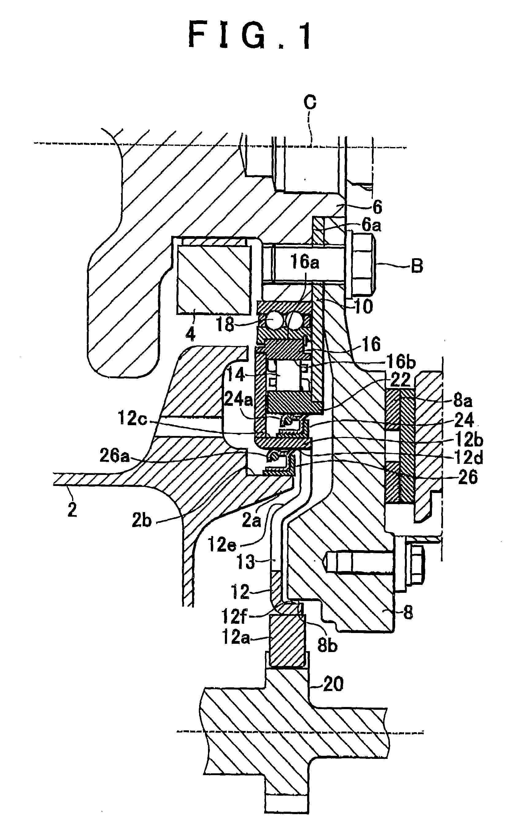
[0034]FIG. 1 is a longitudinal sectional view of a startup torque transmitting mechanism of an internal combustion engine for a vehicle and shows the area on the rear side of the internal combustion engine where power is output to the transmission side.
[0035]According to the first embodiment, as shown in FIG. 1, a rear end (i.e., the right end in the drawing) of a crankshaft 6 that is rotatably supported on a cylinder block side by a ladder beam 4 is arranged above a rear end (i.e., right end in the drawing) of an oil pan 2 of an internal combustion engine. As shown in the drawing, a flywheel 8, an outer race support plate 10 (which can be regarded as a race connecting member in the claims), and a ring gear 12 are all mounted to the rear end portion of the crankshaft 6.
[0036]The flywheel 8, the portion of which is below the center axis C being shown in FIG. 1, is substantially disc-shaped, with the center portion being open in the shape of a circle. A ring-shaped clutch disc 8a, wh...
second embodiment
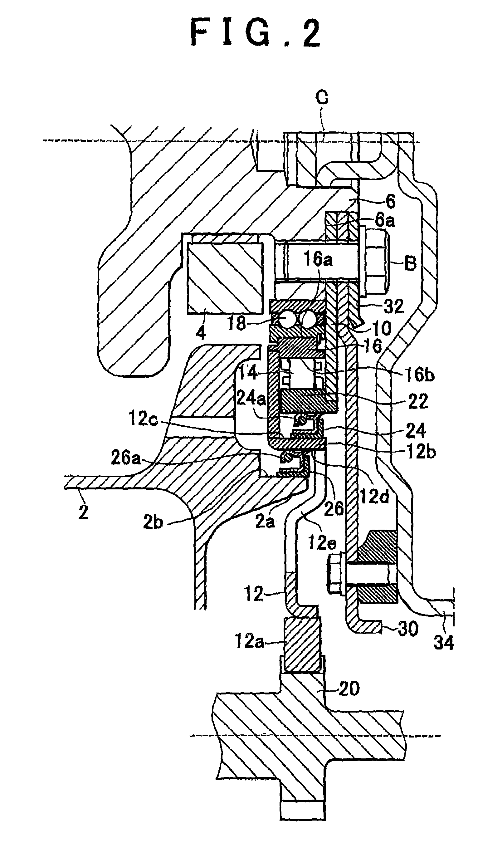
[0057]FIG. 2 is a sectional view of a startup torque transmitting mechanism of an internal combustion engine for a vehicle according to the invention, and shows the area on the rear side of the internal combustion engine where power is output to the transmission side.
[0058]According to the second embodiment, as shown in FIG. 2, a drive plate 30, not the flywheel, is fastened by a bolt to the outer race support plate 10 and the crankshaft 6. The outer race support plate 10 and the drive plate 30 are both fastened, together with a washer plate 32, to the rear end surface (i.e., the right end surface in FIG. 2) 6a of the crankshaft 6 by a bolt B.
[0059]The drive plate 30 is fastened by a bolt at the outer peripheral portion of a cover 34 of a torque converter. As a result, rotation of the crankshaft 6 is transmitted to the torque converter side by the drive plate 30.
[0060]The other structure is the same as that in the first embodiment described above and will therefore be denoted by the...
third embodiment
[0067]Here, a stepped portion 50c, which is the boundary between the separated surface region 50a and the contacting surface region 50b, is set in a position in which, when fastened by the bolt B, sufficient pressing force is applied to the contacting surface region 50b around the bolt B without it buckling. In the third embodiment, the position of a through-hole 50d for the bolt B which is farthest from the center axis C (see FIG. 1 or FIG. 2) is designated as a limit position Pi. This limit position Pi may be closer to the center axis C side than the position shown in FIG. 3.
[0068]A limit position Po to the outside (i.e., the lower side in FIG. 3) of the stepped portion 50c is located on the outermost side (i.e., the lower side in FIG. 3) of the inner race 18a of the bearing 18 that is press-fit to the outer periphery of the crankshaft 6. Therefore, the stepped portion 50c (the starting point P on the inside of the load relieving portion 52) may be set to the position Pi, as shown...
PUM
 Abstract
Description
Claims
Application Information
 - R&D
- Intellectual Property
- Life Sciences
- Materials
- Tech Scout
- Unparalleled Data Quality
- Higher Quality Content
- 60% Fewer Hallucinations
Browse by: Latest US Patents, China's latest patents, Technical Efficacy Thesaurus, Application Domain, Technology Topic, Popular Technical Reports.
© 2025 PatSnap. All rights reserved.Legal|Privacy policy|Modern Slavery Act Transparency Statement|Sitemap|About US| Contact US: help@patsnap.com