Washing and drying machine

a technology of washing machine and drying chamber, which is applied in the direction of washing machine with receptacle, other washing machines, textiles and paper, etc., can solve the problems of increasing energy consumption for drying the laundry, increasing sudden rise of energy costs such as electric charges, so as to reduce the contact time between the laundry and the heated air, the effect of efficient evaporated laundry

Inactive Publication Date: 2008-09-18
SANYO ELECTRIC CO LTD
View PDF1 Cites 16 Cited by
  • Summary
  • Abstract
  • Description
  • Claims
  • Application Information

AI Technical Summary

Benefits of technology

[0006]The present invention has been developed to solve such a conventional technical problem, and an object is to improve a drying efficiency of a laundry in a washing and drying machine, thereby reducing a drying time.
[0007]According to a first aspect of the invention, there is provided a washing and drying machine which washes laundry and dries it after end of the washing, comprising: an outer drum; an inner drum rotated in this outer drum and having a substantially cylindrical shape to constitute a storage chamber therein; a takeout port which is constituted in one end surface of a cylinder of this inner drum in an axial direction and via which the laundry is to be taken or introduced; a plurality of through holes which are formed around a side surface of the cylinder of this inner drum and in the other end surface of the cylinder in the axial direction and from which water is discharged during the washing and through which circulation air for drying circulates during the drying; blowing means for blowing, into the storage chamber, air for drying heated by heating means during the drying; and blowing regulation means for blowing the air for drying into the storage chamber from the side of one end or the other end of the cylinder of the inner drum in the axial direction, allowing the air to flow from the through holes on the other end side or from the one end side, and inhibiting outflow of the air for drying from the other through holes.

Problems solved by technology

Then, much of this air does not return to the storage chamber again, and is blown from the outer drum via the suction port, so that the laundry in the storage chamber cannot sufficiently be brought into contact with the heated air.
In consequence, a long time is required for drying the laundry, and an energy consumption for drying the laundry increases, which causes a problem that energy costs such as electric charges suddenly rise.

Method used


Image

  • Washing and drying machine
  • Washing and drying machine
  • Washing and drying machine

Examples


embodiment 1

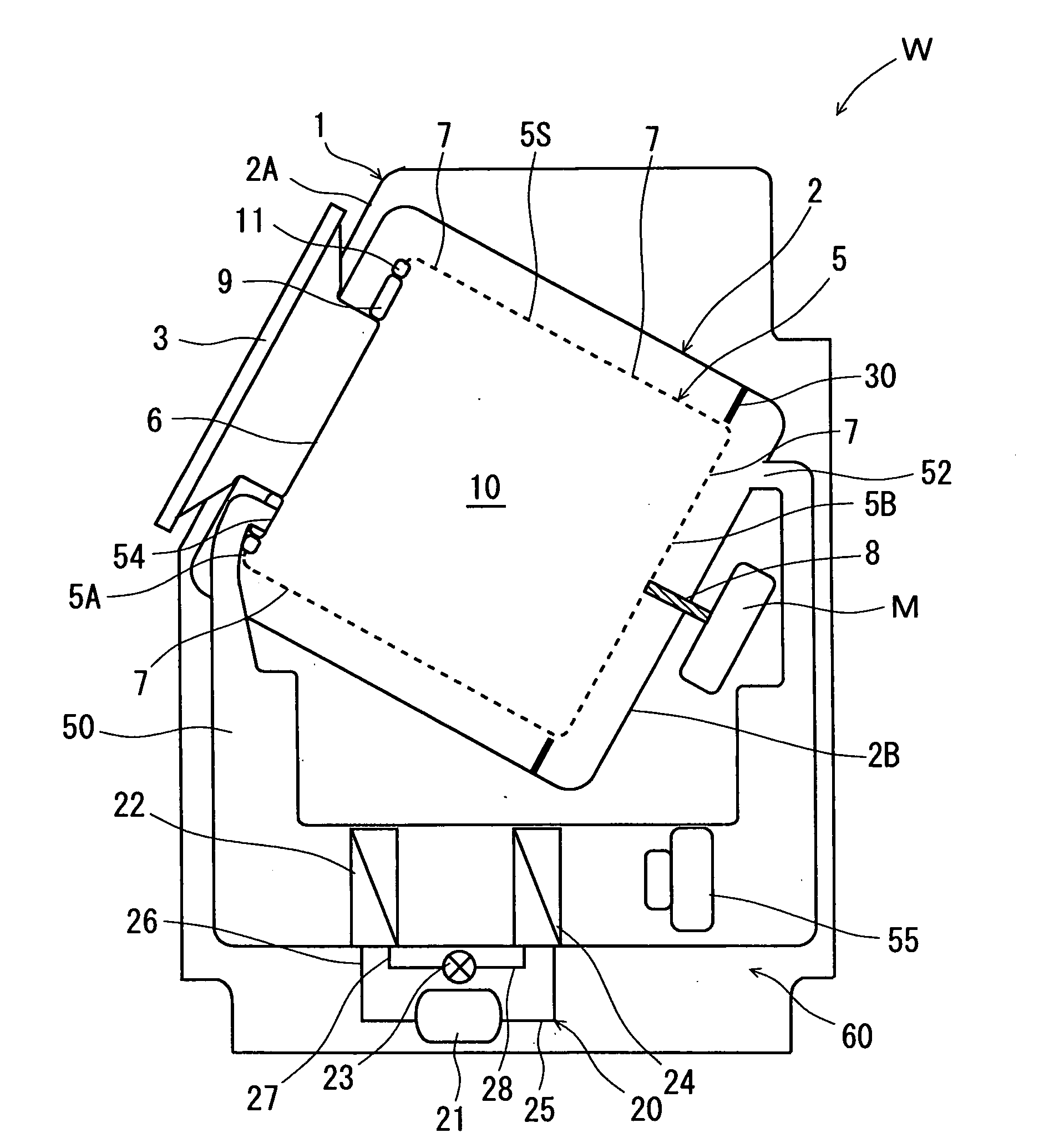
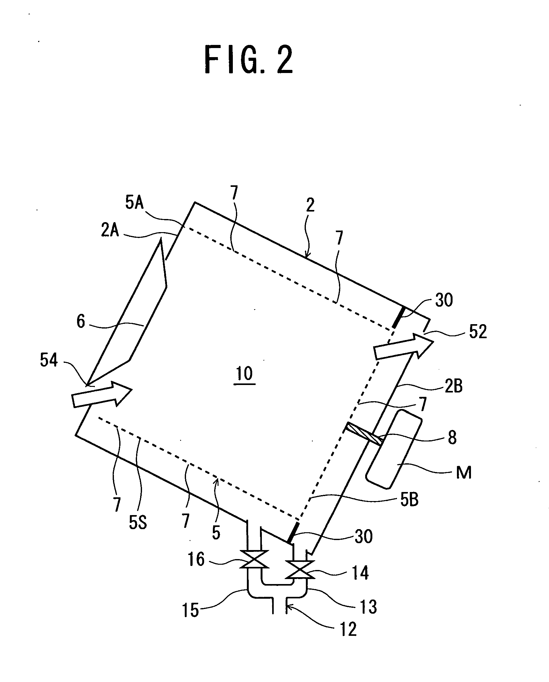
[0031]FIG. 1 is a diagram showing a schematic constitution of a washing and drying machine W according to one embodiment of the present invention, and FIG. 2 is a diagram schematically showing a part of the washing and drying machine W. The washing and drying machine W for use in washing and drying a laundry such as clothing is provided with an opening / closing door 3 which is attached to an upper part of a side surface of a main body 1 forming an outer shell and which openably closes a takeout port 6 for taking or introducing the laundry. An operation panel (not shown) provided with various operation switches and a display section is provided on a side part of the opening / closing door 3 or an upper part of the main body 1.

[0032]In the main body 1, a cylindrical outer drum 2 capable of receiving water and made of a resin is provided so that a cylindrical shaft of this outer drum 2 is disposed in an oblique direction. Then, inside this outer drum 2, a substantially cylindrical inner d...

embodiment 2

[0077]It is to be noted that in Embodiment 1 described above, the blowing regulation means is constituted of the partition wall 30 for dividing the space between the outer drum 2 and the inner drum 5 into the other end 5B side from which the air for drying flows and the other part. However, the present invention is effective, even when an opening / closing member for openably closing through holes 7 . . . around a side surface 5S of an inner drum 5 constitutes the blowing regulation means. FIG. 10 is a schematic diagram showing an outer drum 2 and the inside of the drum in a washing and drying machine Y according to this embodiment. In the present embodiment, an opening / closing member to openably close the through holes 7 . . . around the side surface 5S of the inner drum 5 is constituted of a plurality of valves 80 . . . . It is to be noted that the washing and drying machine Y of the present embodiment is different from the washing and drying machine W of Embodiment 1 described abov...


PUM


Abstract

A washing and drying machine has an object to improve a drying efficiency of a laundry and reduce a drying time, and includes an outer drum; an inner drum rotated in this outer drum and having a substantially cylindrical shape to constitute a storage chamber therein; a takeout port which is constituted in one end surface of a cylinder of this inner drum in an axial direction and via which the laundry is to be taken or introduced; a plurality of through holes which are formed around a side surface of the cylinder of the inner drum and in the other end surface of the cylinder in the axial direction and from which water is discharged during the washing and through which circulation air for drying circulates during the drying; and a blowing regulation unit which blows the air for drying into the storage chamber from the side of one end or the other end of the cylinder of the inner drum in the axial direction and which allows the air to flow from the through holes on the other end side or from the one end side and which inhibits outflow of the air for drying from the other through holes.

Description

BACKGROUND OF THE INVENTION[0001]The present invention relates to a washing and drying machine which includes a storage chamber for receiving a laundry and which washes and dries the laundry in this storage chamber.[0002]In recent years, there has been provided a washing and drying machine which automatically washes and dries a laundry in a storage chamber for receiving the target. In such a washing and drying machine, a cylindrical inner drum provided with a large number of through holes through which air and water can circulate is installed in a cylindrical outer drum capable of receiving the water, and the inside of this inner drum is the storage chamber for receiving the laundry. The inner drum is held in the outer drum so that the inner drum can rotate around a cylindrical shaft of the inner drum connected to a shaft of a driving motor attached to a main body.[0003]Then, when the target to be washed and a detergent having an amount corresponding to the laundry are introduced in...

Claims


Application Information

Patent Timeline
IPC IPC(8): D06F29/00
CPCD06F58/28D06F58/46D06F37/04D06F34/10D06F37/267D06F58/206D06F58/04D06F25/00D06F33/70
Inventor KUWABARA, OSAMU
Owner SANYO ELECTRIC CO LTD
Why Eureka
Try Eureka