Device for separating droplets

A separation liquid and droplet separator technology, which is applied in the field of droplet separation devices, can solve the problems of increased manufacturing costs, expensive equipment, and difficulty in managing the flow conditions of plate components, so as to achieve high evaporation efficiency, reduce droplet formation, and promote The effect of gravity droplet separation

Active Publication Date: 2013-12-25
VAHTERUS OY
View PDF5 Cites 12 Cited by
  • Summary
  • Abstract
  • Description
  • Claims
  • Application Information

AI Technical Summary

Problems solved by technology

In this solution it is difficult to manage the flow conditions in the plate assembly
Having a plate assembly with a special shape also increases the manufacturing cost, whereby the equipment tends to become expensive

Method used


Image

  • Device for separating droplets
  • Device for separating droplets
  • Device for separating droplets

Examples


Embodiment Construction

[0048] For the sake of clarity, the same reference numerals have been used for corresponding parts in the different embodiments. The direction of travel of liquid and vapor is shown with arrows.

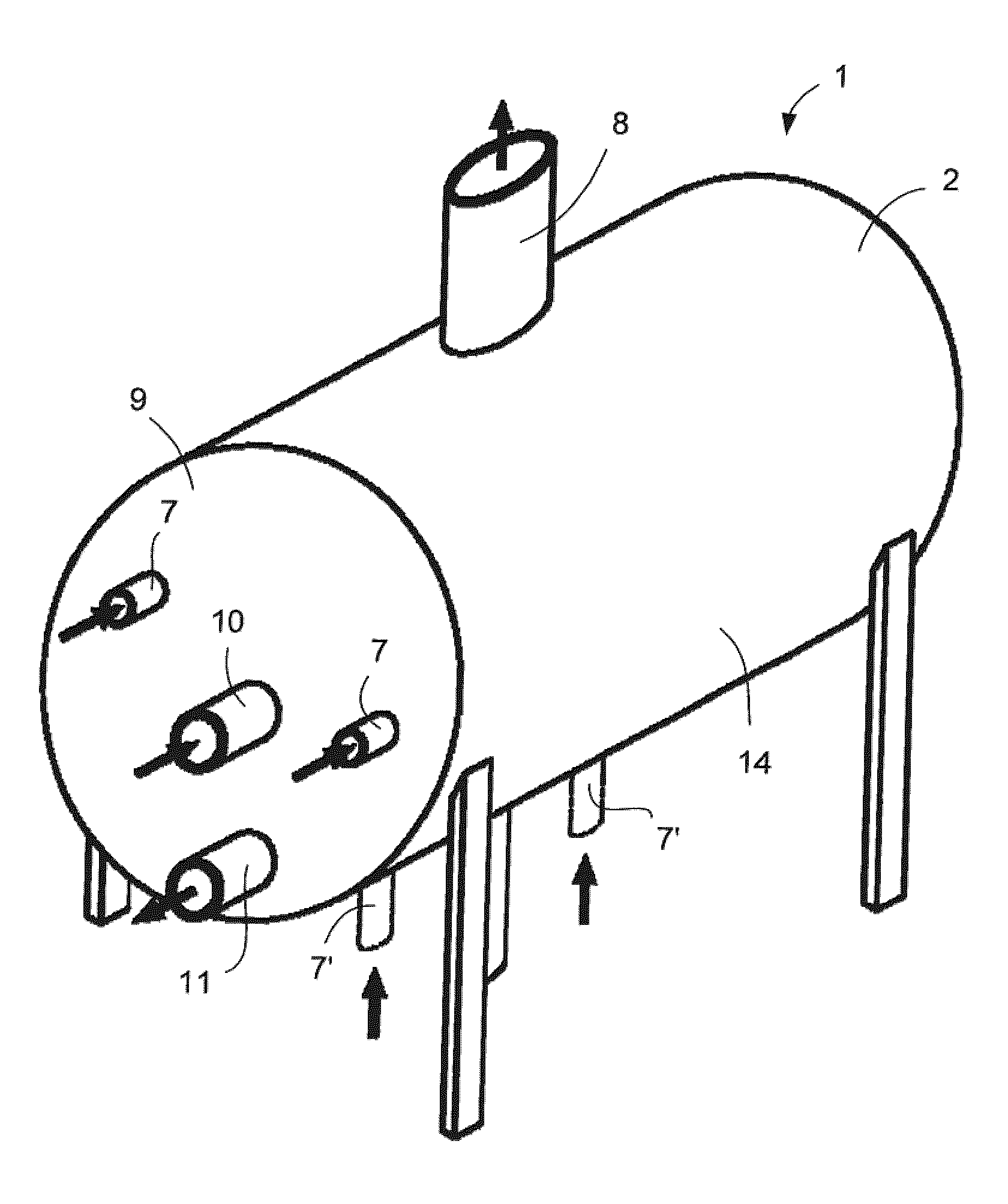
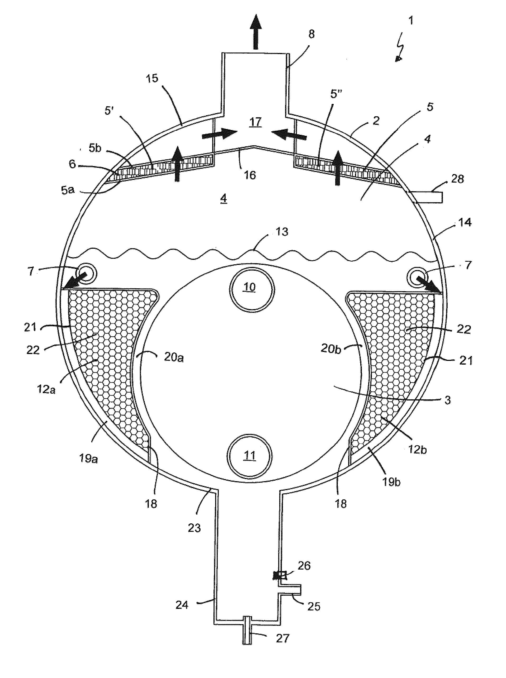
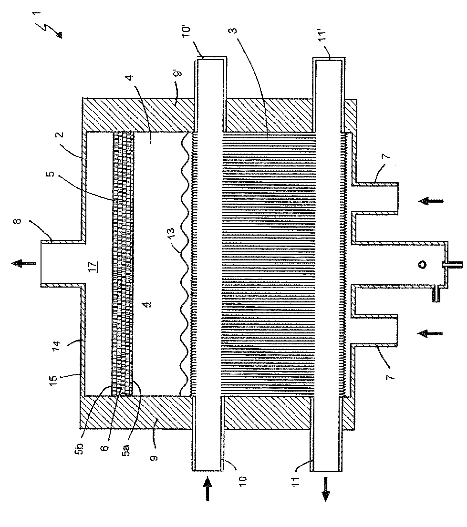
[0049] Figure 1 to Figure 3 Shown is an evaporator droplet separator device 1 having a centrifugal / eccentric fit into an outer housing 2 acting as a frame, i.e. for example into a figure 1 Inside the flat-ended cylinder shown in for example in figure 2 with image 3 Plate&Shell shown in TM A template assembly 3, and a gravity droplet separator 4 and a mist eliminator 5. The demister 5 has two perforated or mesh panels 5a, 5b with steel wool 6 fitted between them. The substance to be vaporized, for example refrigerant, is introduced from the inlet connection 7 into the outer housing 2 . The vaporized substance exits / discharges from the outlet connection 8 in the upper part of the outer housing. With the inlet connection 10 a heating substance is introduced into the plate asse...


PUM


Abstract

The invention relates to a device (1) for separating droplets, which comprises an outer casing (2), which has a substantially horizontal cylindrical shell (14) and substantially vertical ends (9); an inlet connection (7) for a substance to be vapourised for leading a substance to be vapourised into the outer casing; a plate pack (3) functioning as an evaporator, which is arranged inside the outer casing, in its lower part (23); an inlet connection (10) and an outlet connection (11) for a heating substance for leading a heating substance into the plate pack and out of it; a gravitational droplet separator (4), which is arranged inside the outer casing, above the plate pack; an outlet connection (8) for vapourised substance for leading the vapourised substance out of the outer casing from its upper part (15); and one or more filler units (12a, 12b) arranged between the outer casing (2) and the plate pack (3) for decreasing the liquid volume of the substance to be vapourised inside the outer casing. The invention is suited to be used for example as a flooded evaporator (3) of a refrigerating machinery and a thereto related droplet separator (4, 5).

Description

technical field [0001] The present invention relates to a device for separating liquid droplets, for example in a Plate&Shell with a plate structure TM behind the evaporator. The arrangement according to the invention serves to ensure that no liquid droplets are carried over from eg the evaporator to the compressor used in the refrigeration machine. Background technique [0002] An important application of plate heat exchangers is the so-called flooded evaporators and associated droplet separators used in larger refrigeration machinery. The task of the droplet separator is to ensure that no refrigerant droplets are carried over to the compressor of the refrigeration machine. Consequently, the size of the droplet separator is often too large such that gravity droplet separation will occur with sufficient efficiency. The larger size of the droplet separator increases the production cost and mass of the system, and its required space is larger. [0003] Evaporator droplet s...

Claims


Application Information

Patent Timeline
Patent Type & Authority Applications(China)
IPC IPC(8): F25B39/02F25B43/04
CPCF25B39/02F28D21/0017B01D1/305F28F2235/00F28F2250/00F25B39/022F25B43/00
Inventor J·索尼恩V·哈亚维斯托
Owner VAHTERUS OY
Why Eureka
Try Eureka