
Refrigerant System with Pulse Width Modulated Components and Variable Speed Compressor

a technology of pulse width modulation and compressor, which is applied in the direction of machines/engines, liquid fuel engines, lighting and heating apparatus, etc., can solve the problems of low operating speed, low limit of desirable compressor speed reduction, and low efficiency of scroll compressors, so as to achieve the effect of lowering the amount of refrigerant delivered to various locations in the refrigerant cycle and reducing capacity

Inactive Publication Date: 2008-09-18
CARRIER CORP
View PDF30 Cites 54 Cited by
  • Summary
  • Abstract
  • Description
  • Claims
  • Application Information

AI Technical Summary

Benefits of technology

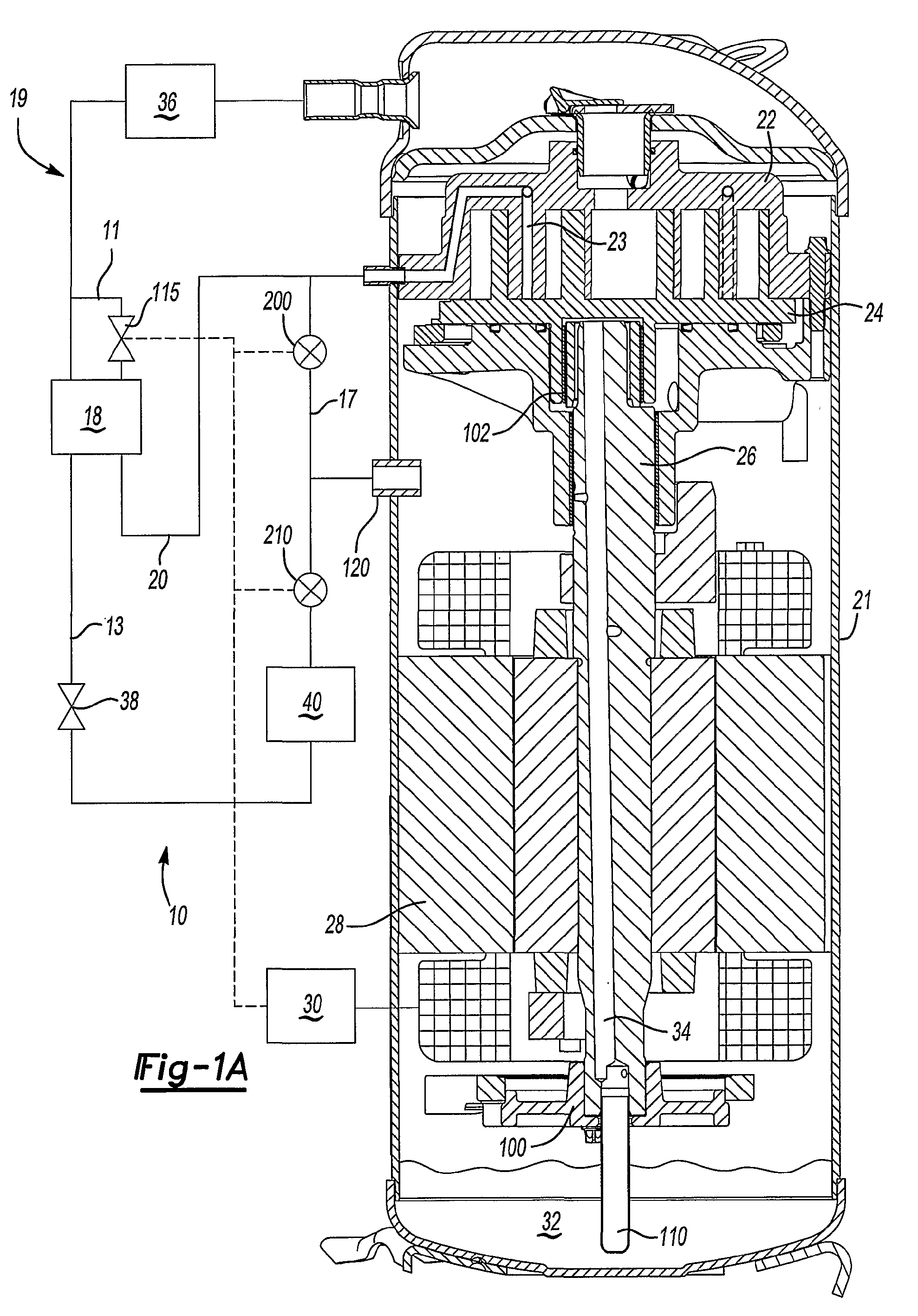
The invention provides a compressor with a variable speed drive that can adjust its speed to maintain optimal conditions without constantly switching on and off. This is particularly useful in refrigerant systems that use scroll compressors. By cycling certain components on and off, the amount of refrigerant delivered to different parts of the system is reduced, which allows for lower capacity without exceeding the safe limits. The invention can be applied to any variable speed compressor.

Problems solved by technology

However, compelling reliability concerns set a lower limit to the desirable compressor speed reduction.
As an example, inadequate lubrication of the compressor elements may present a problem at low operating speeds.
As an example, a scroll compressor could have a dramatic loss in performance due to a loss of radial compliance should it operate below a minimum speed.
These pulse width modulation techniques for control of a valve or internal scroll compression elements have not been utilized, however, in refrigerant systems having a variable speed drive compressor.

Method used


Image

  • Refrigerant System with Pulse Width Modulated Components and Variable Speed Compressor
  • Refrigerant System with Pulse Width Modulated Components and Variable Speed Compressor
  • Refrigerant System with Pulse Width Modulated Components and Variable Speed Compressor

Examples


embodiment 301

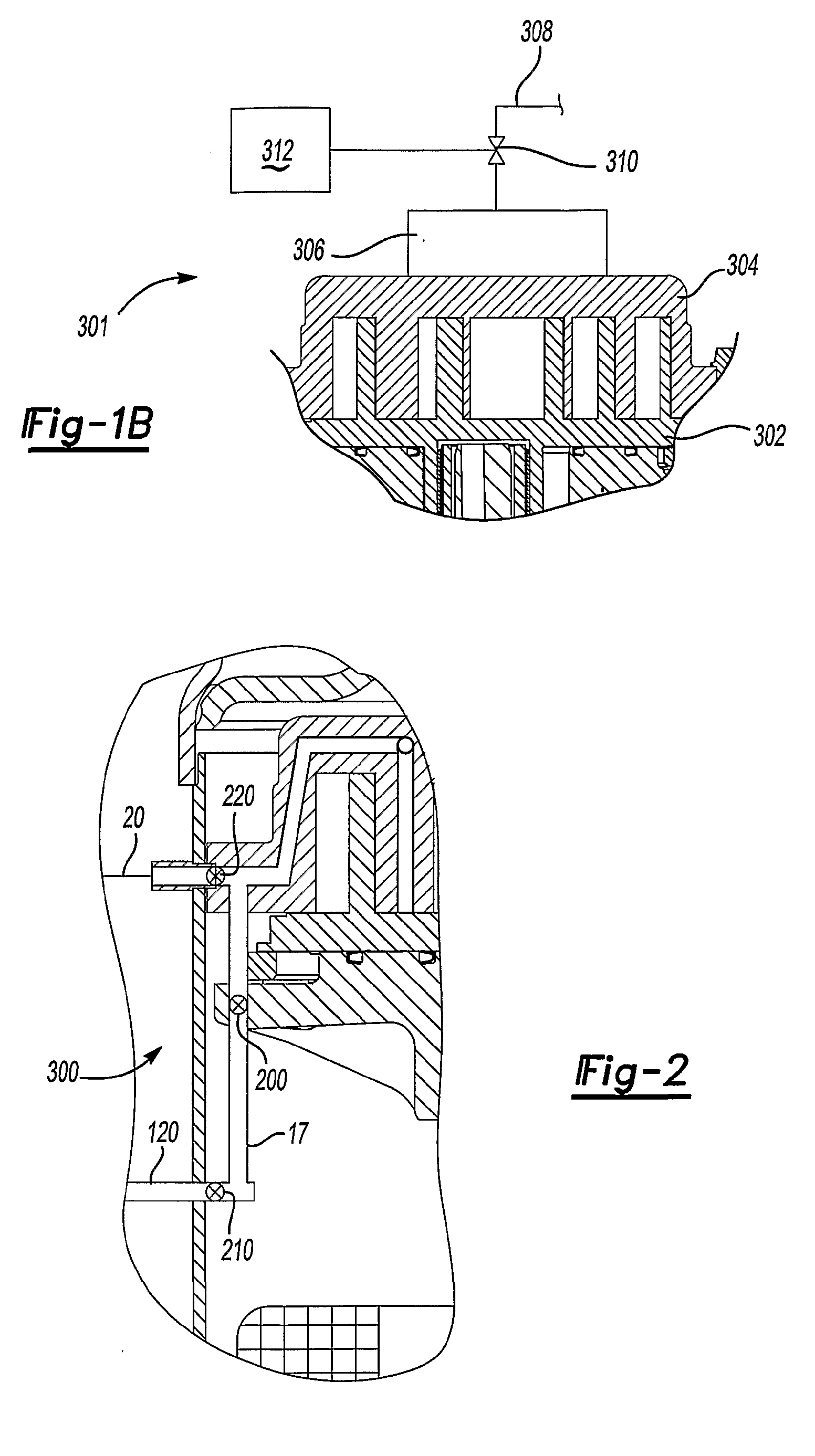
[0021]FIG. 1B shows an embodiment 301, schematically. It is known that the orbiting scroll member 302 and the non-orbiting scroll member 304 may be biased together by a gas in a chamber 306. Opening and closing the valve 310 can control pressure in chamber 306. As shown, the valve 312 communicates via line 308 with another pressure source that is at different pressure than pressure in the chamber 306 when the valve 310 is closed. When the pressure in the chamber 306 is reduced below a certain level the scroll members will separate from each and the amount of refrigerant pumped by the compressor is then reduced. When the pressure in the chamber 306 is increased above certain level the scrolls will come into contact with each other and then the normal compression process will resume. The valve can be controlled by a pulse width modulation control 312. Thus, by modulating the pressure in the chamber 306, the two scroll members 302 and 304 can be allowed to periodically move away from, ...

embodiment 300

[0024]FIG. 2 shows another embodiment 300 wherein the valves 200 and 210 are internal of the compressor shell as are the flow passages. It should be noted that while in FIG. 2 the valves are all shown as located inside the compressor, a compressor designer may choose to locate some of them internally and some of them externally. In addition, the shut-off valve 220 for the economizer line is shown to be separate from the expansion valve. If the valve 220 is located externally, its function can be combined with the use of an expansion valve. Also while valves are shown as separate components, its function can be combined into a single three-way valve as known in the art. Each or some of the valves 220, 200 and 210 can be controlled by pulse width modulation techniques.

[0025]It should be understood that the motor control 30 includes a program that takes in inputs from various locations within the refrigerant system, and determines when a lower speed for the compressor motor would be de...


PUM


Abstract

A variable speed drive is provided for operating a compressor motor in a refrigerant system. When a low load situation has been determined by the refrigerant system controls, the variable speed drive operates the compressor motor at lower speed mode of operation. Further, the operation of the variable speed drive is combined with a pulse width modulation control of different system components. In particular, at least one valve or compressor can be can be rapidly cycled by the control to regulate amount of refrigerant passing through the valve or compressor. Example valves would include a shut-off valve for an economizer cycle, an unloader valve, or a suction modulation valve.

Description

BACKGROUND OF THE INVENTION[0001]This application relates to a control for a refrigerant system having a variable speed compressor, and wherein pulse width modulation technologies are utilized to provide further control over the system.[0002]Refrigerant systems are utilized in many applications to condition an environment. In particular, air conditioners and heat pumps are employed to cool and / or heat air entering the environment. The cooling or heating load of the environment may vary with ambient conditions, occupancy level, other changes in sensible and latent load demands, and as the temperature and / or humidity set points are adjusted by an occupant of the environment.[0003]A feature that is known for improving the efficiency of refrigerant systems is the use of a variable speed drive for the compressor motor. Often, the compressor need not be operated at full speed, such as when the cooling load on the refrigerant system is relatively low. Under such circumstances, it might be ...

Claims


Application Information

Patent Timeline
Patent Type & Authority Applications(United States)
IPC IPC(8): F25B41/04F25B41/00F25B49/00
CPCF04C28/08F04C28/26F04C29/042F25B1/04F25B41/043Y02B30/741F25B2400/13F25B2600/0253F25B2600/0261F25B2600/2521F25B49/025Y02B30/70F25B41/22
Inventor LIFSON, ALEXANDERSRINIVASAN, SRIRAM
Owner CARRIER CORP
Learn More