Three-dimensional-image display system and displaying method
a display system and three-dimensional image technology, applied in the field of three-dimensional image display system and displaying method, can solve the problems of limited region in which the interaction can be expressed, difficult to express live feeling or sense of reality, and give the observer the impression of discomfort and fatigu
- Summary
- Abstract
- Description
- Claims
- Application Information
AI Technical Summary
Benefits of technology
Problems solved by technology
Method used
Image

Examples
first embodiment
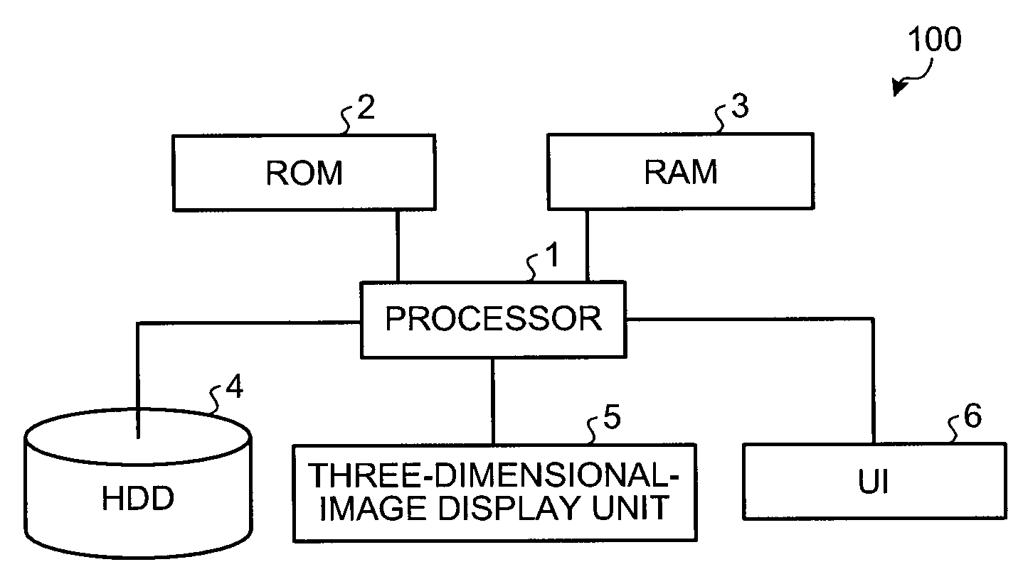
[0036]FIG. 1 is a block diagram of a hardware configuration of a three-dimensional-image display apparatus 100 according to the present invention. The three-dimensional-image display apparatus 100 includes a processor 1 such as a central processing unit (CPU), a graphics processing unit (GPU), a digital signal processor (DSP), a numeric coprocessor, and a physical calculation processor, a read only memory (ROM) 2 that stores BIOS, a random access memory (RAM) 3 that rewritably stores various kinds of data, a hard disk drive (HDD) 4 that stores various kinds of contents concerning a display of a three-dimensional image and stores a three-dimensional-image display program concerning a display of a three-dimensional image, a three-dimensional-image display unit 5 of a space image system such as an integral imaging (II) system that outputs and displays a three-dimensional image, and a user interface (UI) 6 through which a user inputs various kinds of instructions to a main device and di...
second embodiment
[0099]A display mode of the three-dimensional-image display apparatus 100 is explained below with reference to FIGS. 15 to 18.
[0100]FIGS. 15 and 16 depict a state that the spherical virtual object V1 is displayed between the three-dimensional-image display unit 5 set vertically and the transparent flat-shaped real object 7 set vertically at a near position parallel with the display surface of the three-dimensional-image display unit 5. The real object 7 is an actual entity such as a transparent glass sheet and an acrylic sheet. The doted line T in the drawings expresses a motion track of the spherical virtual object V1.
[0101]In this configuration, the real-object position / posture-information storage unit 11 stores information for instructing that the real object 7 is set in parallel with the display surface at a position of a 10 centimeter distance from the display surface of the three-dimensional-image display unit 5, as real-object position / location information. The real-object a...
third embodiment
[0120]As explained above, it is possible to prevent the display of the three-dimensional image at the shielded part of the real object 7. Therefore, a display with little sense of discomfort from the viewpoint of the observer can be achieved, by suppressing the sense of discomfort such as a double image when the position of the shielded part is deviated from the position of the three-dimensional image.
[0121]In the third embodiment, the shielded region is calculated by regenerating by calculation the state that a ray emitted from the three-dimensional-image display unit 5 is irradiated to the CG model. When information corresponding to the shielded region is stored in advance as the real-object position / posture information or the real-object attribute information, the display of the three-dimensional image can be controlled using this information. When a functional unit (a real-object position / posture detector 19) described later that can detect the position and posture of the real ...
PUM
 Abstract
Description
Claims
Application Information
 - R&D
- Intellectual Property
- Life Sciences
- Materials
- Tech Scout
- Unparalleled Data Quality
- Higher Quality Content
- 60% Fewer Hallucinations
Browse by: Latest US Patents, China's latest patents, Technical Efficacy Thesaurus, Application Domain, Technology Topic, Popular Technical Reports.
© 2025 PatSnap. All rights reserved.Legal|Privacy policy|Modern Slavery Act Transparency Statement|Sitemap|About US| Contact US: help@patsnap.com