Method for converting a trimming machine for the preferably three-sided trimming of a stack of sheets

a technology of a trimming machine and a cutting plate, which is applied in the direction of metal-working holders, positioning apparatuses, supports, etc., can solve the problems of cutting knives, die plates, and above all damage, and achieve the effect of simplifying the positioning of a new press di

Inactive Publication Date: 2008-09-11
WOHLENBERG BUCHBINDESYST
View PDF9 Cites 6 Cited by
  • Summary
  • Abstract
  • Description
  • Claims
  • Application Information

AI Technical Summary

Benefits of technology

[0016]Provision is further made to position a new cutting plate automatically under the press die holder as well by means of the positioning device. This is preferably done before a new press die is arranged under the press die plate. The previously replaced cutting plate simplifies the positioning of a new press die under the press die holder, in particular the connection of the die plate to the format plate.

Problems solved by technology

This requires not only time but, above all, experience and skill as well; this is because, above all, the die plate of the press die, which is normally formed of paperboard, must be adhesively bonded underneath a format plate of the press die, generally formed of hardwood, in an accurate relative position in relation to the format plate, since, even in the event of small deviations from the intended position, bonding the die plate under the format plate would result in damage to the die plate and above all to the cutting knives.

Method used


Image

  • Method for converting a trimming machine for the preferably three-sided trimming of a stack of sheets
  • Method for converting a trimming machine for the preferably three-sided trimming of a stack of sheets
  • Method for converting a trimming machine for the preferably three-sided trimming of a stack of sheets

Examples


Embodiment Construction

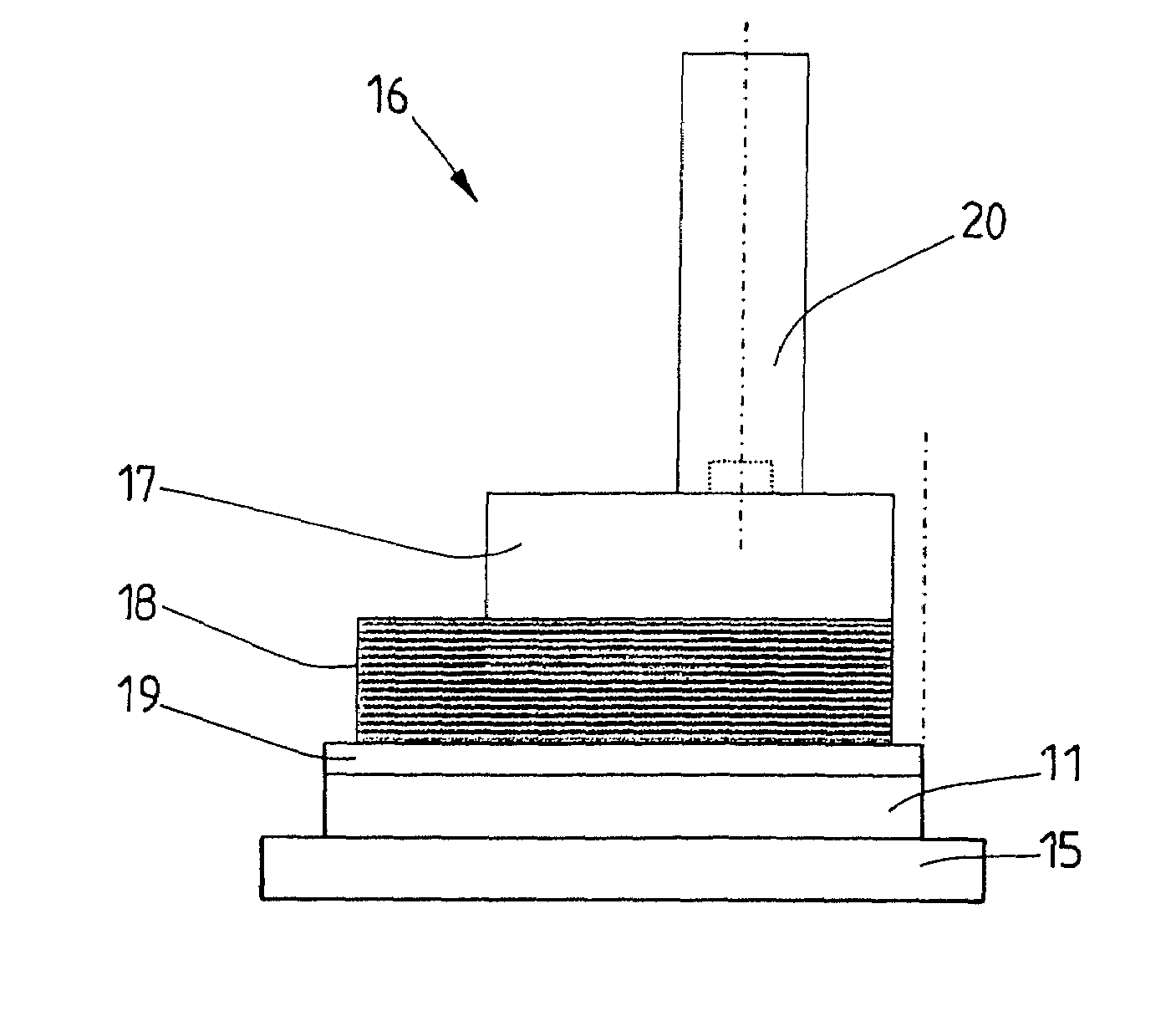
[0028]The invention will be explained below by using a trimming machine designed as an automatic three-knife trimmer. By using the automatic three-knife trimmer 10, a stack of sheets, which, for example, is a stack of printed sheets 11 for the production of bound printed products (books or the like), can be trimmed on three sides.

[0029]The automatic three-knife trimmer 10 has a feeder 12, illustrated only schematically in FIGS. 2 to 7, with which stacks of printed sheets 11 can be fed in preferably individually, so that a stack of printed sheets 11 is always available for trimming in the automatic three-knife trimmer 10.

[0030]The automatic three-knife trimmer 10 has three cutting knives 13 and 14, specifically two parallel cutting knives 13 running longitudinally in the feed direction of the stack of printed sheets 11 and a transversely oriented cutting knife 14. The cutting knives 13 and 14, thus running at right angles to one another in each case, are used for the purpose of trimm...


PUM

PropertyMeasurementUnit
dimensionaaaaaaaaaa
compressaaaaaaaaaa
timeaaaaaaaaaa

Abstract

The invention provides for the replacement of the cutting plate (15) and the press die (16) to be carried out automatically, specifically with the aid of a positioning device for positioning the stack of printed sheets (11) to be trimmed under the press die (16). In this way, the automatic conversion of the automatic three-knife trimmer for a format change is possible without a significant change to the automatic three-knife trimmer. Only the control system of the positioning device has to be changed and expanded. The positioning device (21) automatically ensures that the new press die (16) and the new cutting plate (15) are positioned exactly. In particular, the positioning of the die plate (19) under the format plate (18) can be carried out automatically by means of the positioning device with the required high accuracy, to be specific with higher accuracy than would be possible manually.

Description

STATEMENT OF RELATED APPLICATIONS[0001]This patent application claims convention priority on and is based on German Patent Application No. 10 2007 011 391.0 having a filing date of 7 Mar. 2007 and German Patent Application No. 10 2007 025 756.4 having a filing date of 1 Jun. 2007, both of which are incorporated herein by this reference in their entireties.BACKGROUND OF THE INVENTION[0002]1. Technical Field[0003]The invention relates to a method for converting a trimming machine having a press die and a cutting plate for the preferably three-sided trimming of a stack of sheets. This invention relates to a method for converting a trimming machine having a press die and a cutting plate for the preferably multi-sided trimming of a stack of sheets, the cutting plate and the press die being replaced in order to change the format of the stack of sheets. This invention relates to a method for converting a trimming machine having a press die and a cutting plate for the multi-sided trimming o...

Claims


Application Information

Patent Timeline
Patent Type & Authority Applications(United States)
IPC IPC(8): B26D7/02B26D1/09B26D7/06B26D7/32
CPCB26D1/09B26D7/02B26D7/06B26D2007/0056B26D2007/0081Y10T483/13Y10S83/954Y10T483/16Y10T483/17Y10T483/1729Y10T483/10B26D2007/322Y10T83/05Y10T83/0448
Inventor HANSMANN, ROLFLANGE, ANDREASLUSTERMANN, BERND
Owner WOHLENBERG BUCHBINDESYST
Why Eureka
Try Eureka