
Constant load fastener

a constant load and fastener technology, applied in the direction of fastening means, securing devices, screws, etc., can solve the problems of slipping, tendency to lose tension, and application of this method

Inactive Publication Date: 2008-09-04
TINI ALLOY
View PDF99 Cites 21 Cited by
  • Summary
  • Abstract
  • Description
  • Claims
  • Application Information

AI Technical Summary

Benefits of technology

[0012]Described herein are new and improved fasteners and devices for securing together several components in such a way that the load applied to the components is constant or nearly

Problems solved by technology

This is often not true: loads applied by this method may vary by a large factor from one installation to another.
Bolts subjected to high stress also are subject to ‘creep,’ a tendency to lose tension with time, due to a gradual relaxation of the material of which the bolts are made.
For example, fasteners exposed to changes in temperature (or regions having different temperatures) may experience differential thermal expansion that can cause the fastener to break.
This method may be incompatible with the purpose of the joint.
For example, this method may result in contamination from lubricants in a bolt used on a space mission.
Because Belleville washers generally have spring characteristics (force versus displacement) that are very different from that of the bolt, the forces generated are sufficient for limited applications.

Method used


Image

  • Constant load fastener
  • Constant load fastener
  • Constant load fastener

Examples


Embodiment Construction

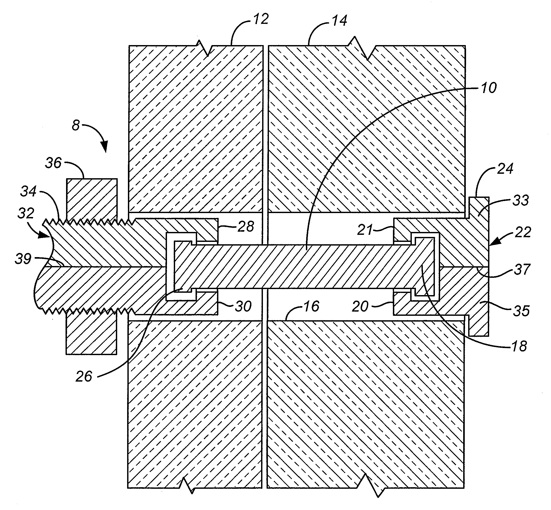
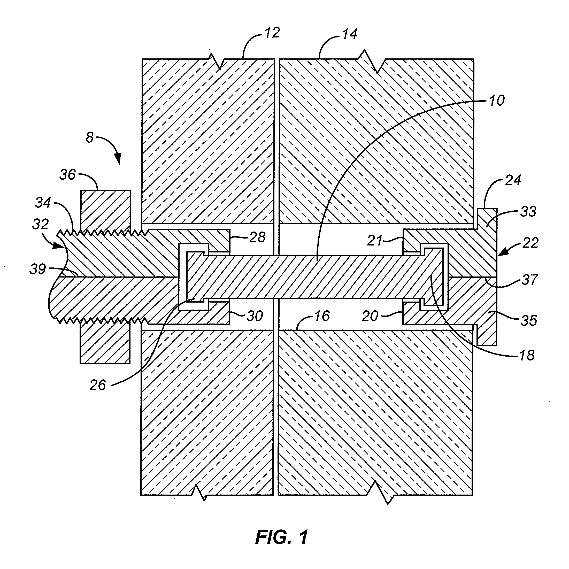
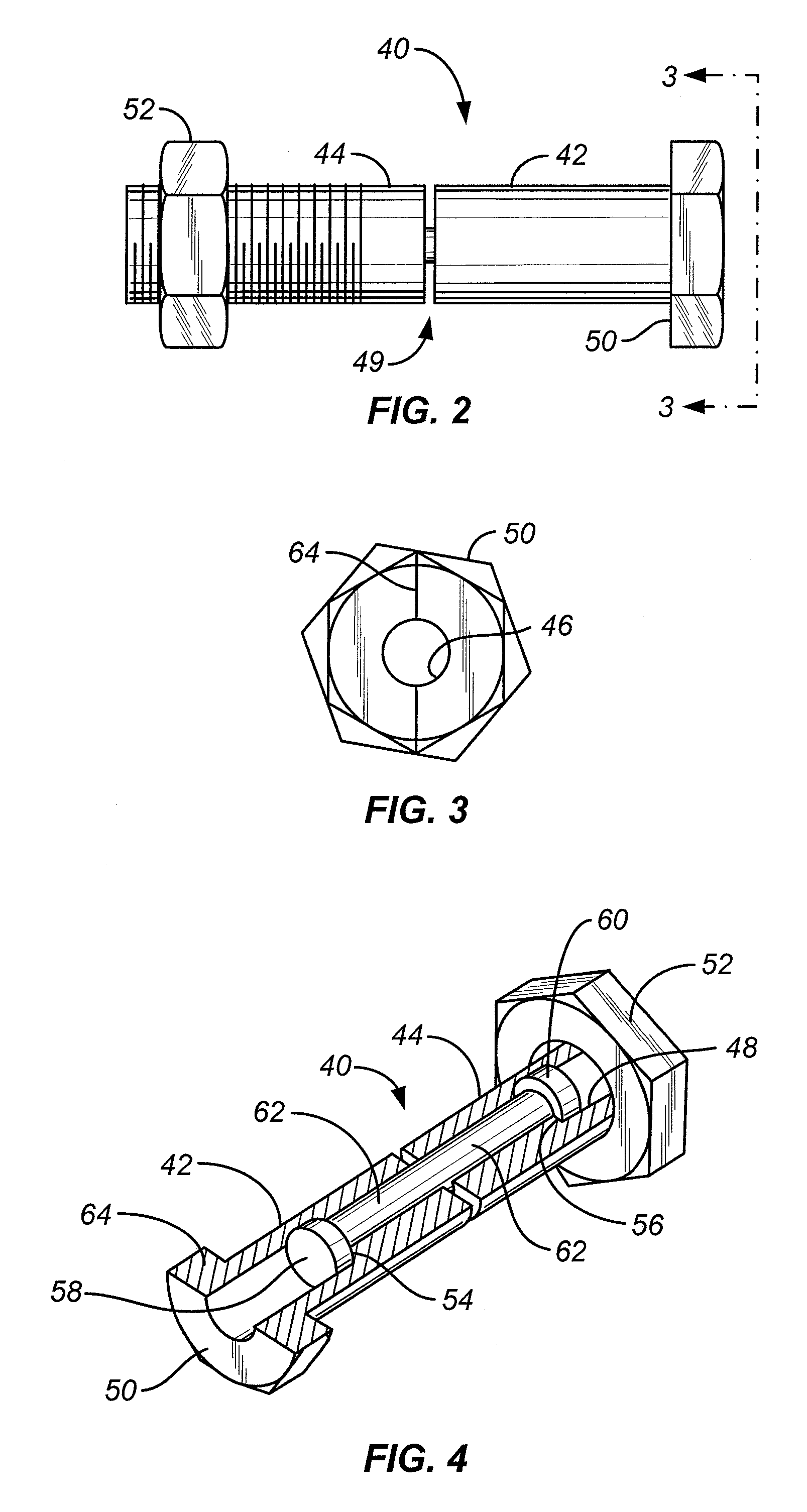
[0030]In general, the fasteners described herein include a hyperelastic shaft that is configured to receive the fastening load generated when the fastener secures two or more structures together. The fasteners also include a retainer coupled at each end of the hyperelastic shaft. The retainers typically connect to, and retain the structure(s) to be fastened by the fastener. The retainers therefore include one or more load bearing surface that is configured to contact a structure to be retained. The two retainers couple to the ends of the shaft and transfer the load to the shaft. These retainers do not typically directly contact each other, but are connected by the shaft.

[0031]The hyperelastic shaft is typically a shape memory alloy (SMA) shaft that is fabricated as a single crystal. Single crystal SMAs are defined herein as “hyperelastic” because they can undergo recoverable distortions that are much larger than can be achieved by conventional materials. Such distortions are greater...


PUM


Abstract

Described herein are fasteners and devices for securing together several components so that the load applied to the components is constant or nearly constant. The fasteners described herein include a hyperelastic member having first end to which a first retainer is coupled and a second end to which a second retainer is coupled. The retainers are configured to contact the structures being fastened and transfer the load from the structures to the hyperelastic member. The hyperelastic member may be an elongate shaft (e.g., a rod, cylinder, strut, etc.), and is a shape memory alloy that is typically fabricated as a single crystal.

Description

CROSS-REFERENCE TO RELATED APPLICATIONS[0001]This application is a continuation-in-part of U.S. patent application Ser. No. 11 / 526,138, filed on Sep. 22, 2006.BACKGROUND OF THE INVENTION[0002]1. Field of the Invention[0003]This invention relates to mechanical devices that have a component in which large recoverable distortions at constant force provide a constant load fastening.[0004]2. Description of Related Art[0005]Ordinary bolts such as those made of steel and various alloys, used to secure two or more components together, are generally tightened by applying a known torque to the nut or stud. It is assumed that the holding force, or load, applied to the components of the joint is proportional to the torque. This is often not true: loads applied by this method may vary by a large factor from one installation to another.[0006]Bolts subjected to high stress also are subject to ‘creep,’ a tendency to lose tension with time, due to a gradual relaxation of the material of which the bo...

Claims


Application Information

Patent Timeline
IPC IPC(8): F16B31/04F16B35/02F16B29/00
CPCF16B1/0014F16B35/02F16B31/04F16B2200/77
Inventor JOHNSON, ALFRED DAVIDBOKAIE, MICHAEL D.MARTYNOV, VALERY
Owner TINI ALLOY
Learn More