
Stand

a technology for standing and supporting posts, applied in the field of standing, can solve the problems of difficult movement and adjustment of stands, difficult storage, transportation and repositioning, and heavy weight of workouts such as martial arts, and achieve the effects of promoting the stability of the stand, reducing vibration transmission, and reducing the transmission of vibrations

Inactive Publication Date: 2008-09-04
CONSIDINE GARY
View PDF10 Cites 14 Cited by
  • Summary
  • Abstract
  • Description
  • Claims
  • Application Information

AI Technical Summary

Benefits of technology

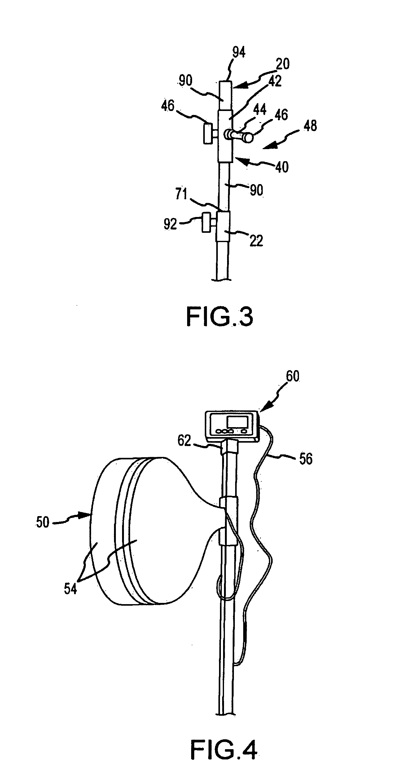
[0014]The base portion may also include a height adjustment member that is movable relative to the central member. The height adjustment member may be aligned with the central member to extend vertically away from the central member. In this manner, the height adjustment member can extend linearly away from or toward the central member in a telescoping manner to increase or decrease the overall height of the base portion.
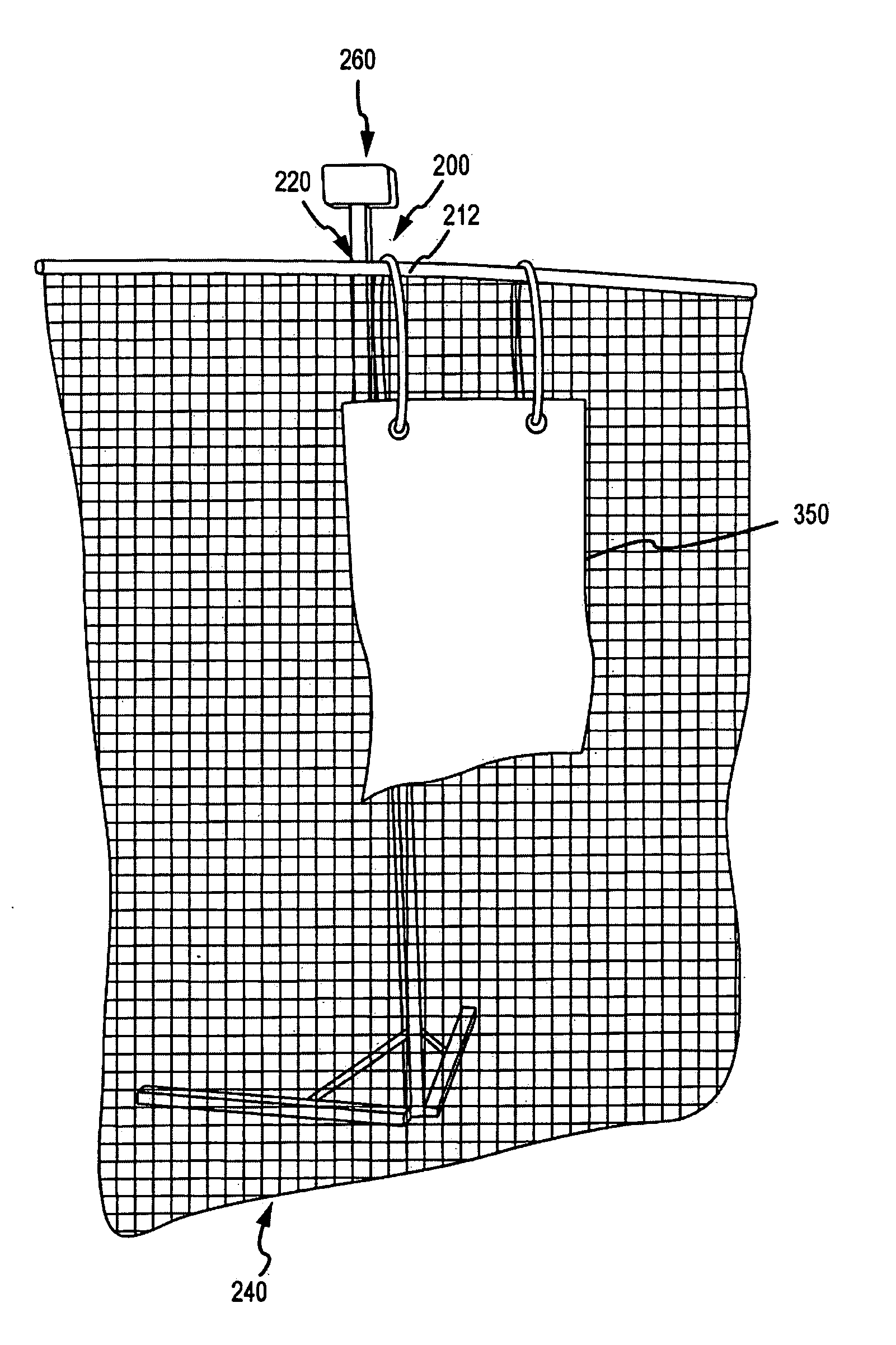
[0017]The accessory receiving portion may be provided as a generally tubular member extending substantially perpendicularly from the base portion. The accessory receiving portion may define an interior channel that may be sized to receive a portion of an accessory, such as a target. The accessory receiving portion can include a slot that extends from an open end, opposite the base portion, and a clamp mechanism that extends about the accessory receiving portion proximate the open end. The cross-sectional area of the channel may then be reduced by tightening the clamp mechanism into a locked position which reduces the width of the slot.
[0021]In some embodiments, the stand may further include first and second secondary connectors removably and adjustably coupleable to the accessory extension member. The first and second secondary connectors may be removably securable to the extension member via various locking mechanisms and positionable at any of various locations along the extension member. Each target may be provided to be removably securable to a respective one of the first and second secondary connectors. Each target may also be provided in a manner that permits each target to be rotated to a particular angle irrespective of the angle of the other target.
[0023]In some embodiments, the stand may be provided in a heavier and more durable fashion for commercial applications and sports uses. The base portion may include an elongate central member and elongate stabilizer members. Connector plates are coupled to a bottom end portion of the central member and a base plate along side and bottom edge portions of the connector plates. The stabilizer members are coupled to the connector plates at first end portions, respectively, such that the stabilizer members can pivot about their first end portions relative to the central member.
[0025]In certain embodiments, the stability of the stand may be further promoted by engaging relatively high friction pads at the distal end portions of the stabilizer members. It is contemplated that the high friction pads may be provided in the form of foot members formed from various materials, including generally resilient materials that include natural and synthetic rubbers as well as some polymer materials. An additional friction pad may be placed on a bottom surface of the base plate for additional stability. The friction pads may further limit the transmission of vibrations from the stand to the operating surface, which may tend to reduce noise emitted from use of the stand, and may further limit damage to the operating surface.

Problems solved by technology

Conventional sports stands for receiving impacts associated with athletic workouts, such as martial arts workouts, can be bulky and heavy.
Accordingly, these stands are often difficult to store, transport and reposition.
Such targets can weigh upwards of approximately 200 lbs., which can make the stands difficult to move and adjust.
Some conventional stands require often complex disassembly prior to storing or moving the stands.
Additionally, many conventional sporting stands require a permanent installation.
Also, with many known sporting stands, customization of the stands to accommodate different sports and athletic workouts can be difficult.
For example, many known sports stands are configured to receive impacts associated with one specific sporting activity and cannot be modified for use with other sporting activities.
Moreover, this Summary is not intended for use as an aid in determining the scope of the claimed subject matter.
The friction pads may further limit the transmission of vibrations from the stand to the operating surface, which may tend to reduce noise emitted from use of the stand, and may further limit damage to the operating surface.

Method used


Image

  • Stand
  • Stand
  • Stand

Examples


Embodiment Construction

[0053]Embodiments are described more fully below with reference to the accompanying figures, which form a part hereof and show, by way of illustration, specific exemplary embodiments. These embodiments are disclosed in sufficient detail to enable those skilled in the art to practice the invention. However, embodiments may be implemented in many different forms and should not be construed as being limited to the embodiments set forth herein. The following detailed description is, therefore, not to be taken in a limiting sense.

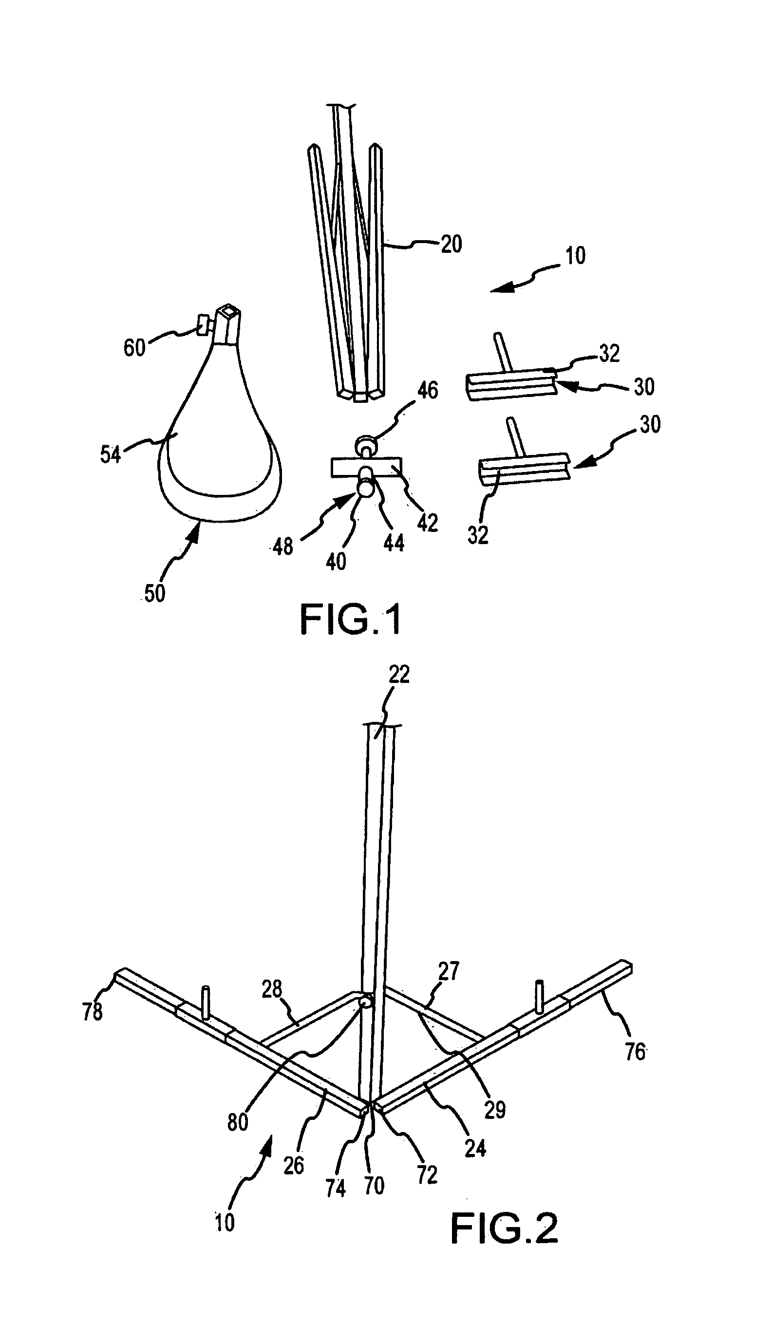
[0054]With reference to FIG. 1 and according to one contemplated embodiment of a stand 10 includes a collapsible base portion 20, weight mounts 30, connector 40, target 50, and impact sensing module 60.

[0055]The base portion 20, shown in a collapsed state in FIG. 1 and an expanded state in FIG. 2, includes an elongate central member 22 and elongate stabilizer members 24, 26. The stabilizer members 24, 26 are pivotally coupled to a bottom end portion 70 of the ce...


PUM


Abstract

A system is provided for supporting one or more objects above an operating surface. A central frame extends upwardly from a base and supports one or more attachment members for supporting a variety of objects. In one aspect the objects supported by the system are targets that receive striking forces from external sources. A force measuring device may be associated with the targets. The central frame may be adjustable so that the height of the objects supported by the system may be varied. The base may include stabilizer members that are movable between collapsed and extended positions. Weight of various types may be associated with the stabilizer members to promote stability of the system. Wheels may be associated with the base to enable transport of the system from one location to another.

Description

CROSS-REFERENCE TO RELATED PATENT APPLICATIONS[0001]The invention claims priority from U.S. Provisional Patent Application No. 60 / 878,734 entitled STAND by Gary Considine, Rita Sever, Jeff Dankworth, Greg Snyder, and Patricia Brenner, filed on Jan. 4, 2007, which Provisional Patent Application is hereby incorporated by reference in its entirety.OTHER RELATED PATENTS[0002]U.S. Pat. No. 7,308,818 (the '818 patent), entitled “Impact-Sensing and Measurement Systems, Methods for Using Same, and Related Business Methods,” issued on Dec. 18, 2007, is hereby incorporated by reference herein in its entirety. U.S. patent application Ser. No. 12 / 004,337 (the '337 patent Application), entitled “Impact-Sensing and Measurement Systems, Methods for Using Same, and Related Business Methods,” filed on Dec. 18, 2007, is hereby incorporated by reference herein in its entirety.[0003]In the event of a conflict, the subject matter explicitly recited or shown herein controls over any subject matter incorp...

Claims


Application Information

Patent Timeline
IPC IPC(8): F16M11/08
CPCA63B24/0021F16M2200/08A63B69/0002A63B69/002A63B69/36A63B71/06A63B2024/0037A63B2210/50F16M11/34F16M11/42F16M11/08F16M11/105F16M11/242F16M11/28F16M2200/022F16M2200/027F16M2200/028A63B63/00
Inventor CONSIDINE, GARY
Owner CONSIDINE GARY
Learn More