Low Power Write Driver for a Magnetic Disk Drive

a magnetic disk drive and low power technology, applied in the direction of h-bridge head driver circuit, data recording, instruments, etc., can solve the problems of limiting the benefits of efficiently and accurately writing data to the disk, excessive power dissipation at the read/write head and in the write driver circuitry, and exacerbated limitation, so as to reduce the steady-state power dissipation

Inactive Publication Date: 2008-08-28
TEXAS INSTR INC
View PDF19 Cites 20 Cited by
  • Summary
  • Abstract
  • Description
  • Claims
  • Application Information

AI Technical Summary

Benefits of technology

[0014]It is therefore an object of this invention to provide write driver circuitry for a disk drive system that reduces the steady-state power dissipation.
[0015]It is a further object of this invention to provide such write driver circuitry in which ample head launch voltage and overshoot current is available for high data rate situations.
[0018]The present invention may be implemented into a write driver circuit for a disk drive, by providing a steady-state H-bridge drive circuit for the write head in parallel with a boost H-bridge drive circuit. The steady-state H-bridge has a sink voltage (i.e., lower reference voltage) that is not as low a voltage as that for the boost H-bridge. As such, the voltage drop across the steady-state drive circuit and load in the steady-state is reduced from the voltage drop across the boost H-bridge drive circuit and load, reducing the power dissipation in the steady-state portion of the write pulse.

Problems solved by technology

And, as known in the art, inadequate head launch voltage will limit the applied overshoot current, and thus limit the benefits of that overshoot in efficiently and accurately writing data to the disk.
But because the write driver circuit must accommodate the highest specified data rate as the worst case (i.e., the highest overshoot current and head launch voltage), the Vcc power supply voltage will necessarily be over-designed for nominal data rates, and thus will necessarily be over-designed for the vast majority of disk write operations.
Especially with the small form factor disk drive systems that are now popular in the industry, and also considering the thermal effects on the low fly heights of the read-write heads in modern disk drives, excessive power dissipation at the read / write head and in the write driver circuitry is undesirable.
This limitation is exacerbated in portable systems including a disk drive, such as digital audio players, where excessive power dissipation undesirably shortens battery life.

Method used


Image

  • Low Power Write Driver for a Magnetic Disk Drive
  • Low Power Write Driver for a Magnetic Disk Drive
  • Low Power Write Driver for a Magnetic Disk Drive

Examples


Embodiment Construction

[0024]The present invention will be described in connection with its preferred embodiment, namely as implemented into a disk drive system for a computer or other digital system, because it is contemplated that this invention will be especially beneficial when used in such an application. However, it is also contemplated that this invention may provide important benefits and advantages in other applications besides that described in this specification. Accordingly, it is to be understood that the following description is provided by way of example only, and is not intended to limit the true scope of this invention as claimed.

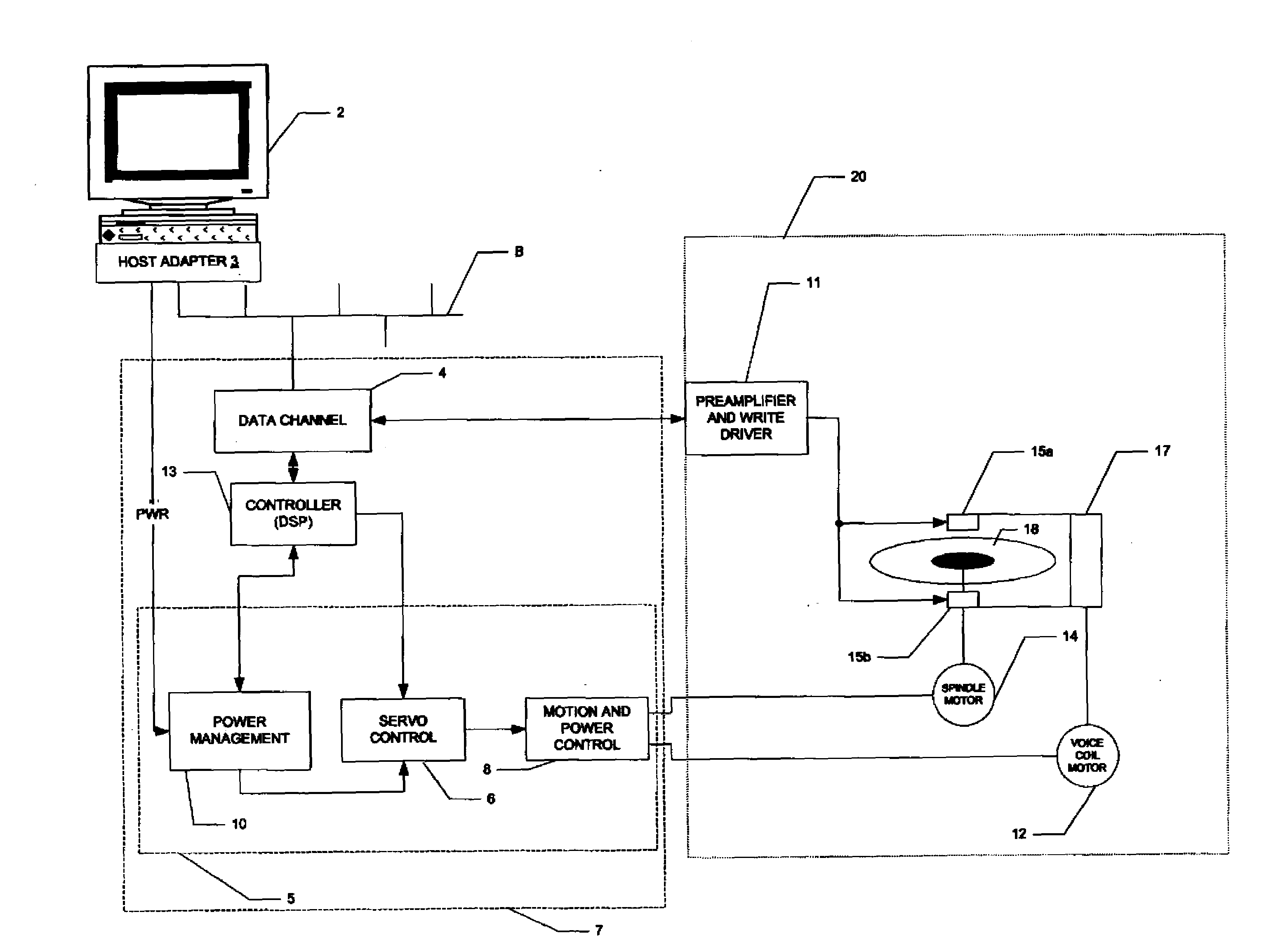
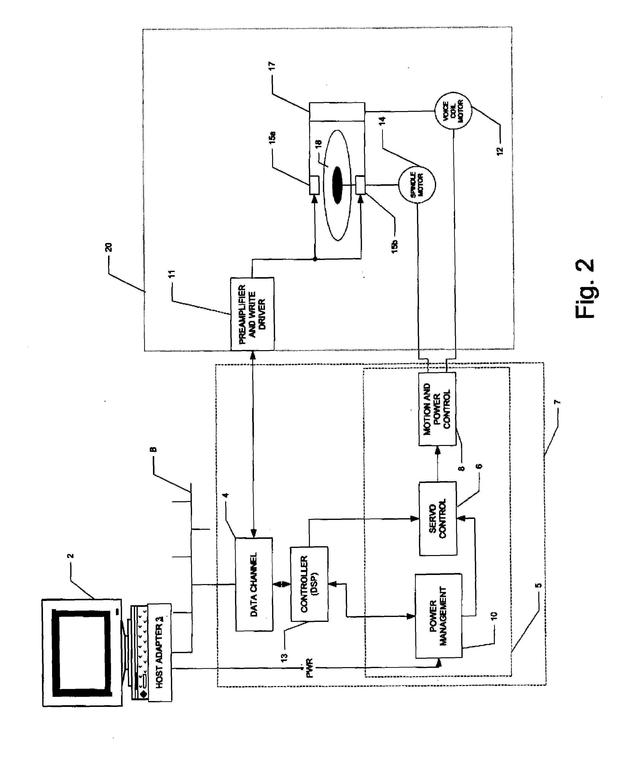
[0025]FIG. 2 illustrates an example of a computer including a disk drive system, into which the preferred embodiment of the invention is implemented. In this example, personal computer or workstation 2 is realized in the conventional manner, including the appropriate central processing unit (CPU), random access memory (RAM), video and sound cards or functionality...


PUM

PropertyMeasurementUnit
total voltageaaaaaaaaaa
voltageaaaaaaaaaa
bias voltagesaaaaaaaaaa

Abstract

A write driver (11) for a disk drive system is disclosed. The write driver (11) includes a normal H-bridge drive circuit (30) and a boost H-bridge drive circuit (32). The normal and boost H-bridge drive circuits (30, 32) are both biased from a Vcc power supply; however, system ground (GND) biases the normal H-bridge drive circuit (30), while a Vee power supply voltage, which is negative relative to system ground (GND), biases the boost H-bridge drive circuit (32). Diodes (46Y, 46X) are provided in the pull-down paths of the normal H-bridge drive circuit (30). During the boost portion of the write cycle, both of the normal and boost H-bridge drive circuits (30, 32) are on, and the pull-down current from the write head (HD) is conducted to the Vee power supply voltage. After the boost portion of the cycle, and thus after the desired overshoot current has been applied, only the normal H-bridge drive circuit (30) drives the steady-state write current, which is conducted to system ground (GND).

Description

CROSS-REFERENCE TO RELATED APPLICATIONS[0001]Not applicable.STATEMENT REGARDING FEDERALLY SPONSORED RESEARCH OR DEVELOPMENT[0002]Not applicable.BACKGROUND OF THE INVENTION[0003]This invention is in the field of disk drive systems, and is more specifically directed to write driver circuitry in such disk drives.[0004]Magnetic disk drive technology is the predominant mass non-volatile storage technology in modern personal computer systems, and continues to be an important storage technology for mass storage applications in other devices, such as portable digital audio players. As is fundamental in the field of magnetic disk drives, data is written by magnetizing a location (“domain”) of a layer of ferromagnetic material disposed at the surface of a disk platter. Each magnetized domain forms a magnetic dipole, with the stored data value corresponding to the orientation of that dipole. The “writing” of a data bit to a domain is typically accomplished by applying a current to a small elec...

Claims


Application Information

Patent Timeline
Patent Type & Authority Applications(United States)
IPC IPC(8): G11B5/09
CPCG11B5/022G11B2005/0018G11B5/09
Inventor HASHIZUME, MOTOMU
Owner TEXAS INSTR INC
Why Eureka
Try Eureka