
Leak Resistant Siphoning Device For Use in Fluid Transfer

a siphoning device and fluid transfer technology, applied in the direction of liquid handling, packaging goods, transportation and packaging, etc., can solve the problems of low cost basters that do not adequately contain liquid, liquid and/or partial solids drawn up into the hollow member often leak out of the baster unintentionally, and achieve less fluid spillage , improve the seal, and add to the safety and reliability of the function

Inactive Publication Date: 2008-08-28
SPRIEGEL ANDREW R +1
View PDF13 Cites 15 Cited by
  • Summary
  • Abstract
  • Description
  • Claims
  • Application Information

AI Technical Summary

Benefits of technology

[0013]The present invention relates to an improved siphoning device for liquids and / or partial solids, particularly of the type used for basting foods. The present invention offers a low cost means to keep the baster from leaking or splattering hot liquid or partial solids by the means of a check valve assembly just ahead of the bulb end of the liquid tube.
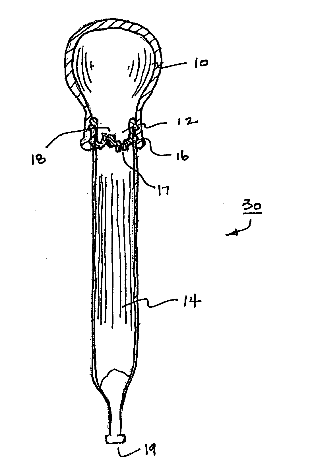
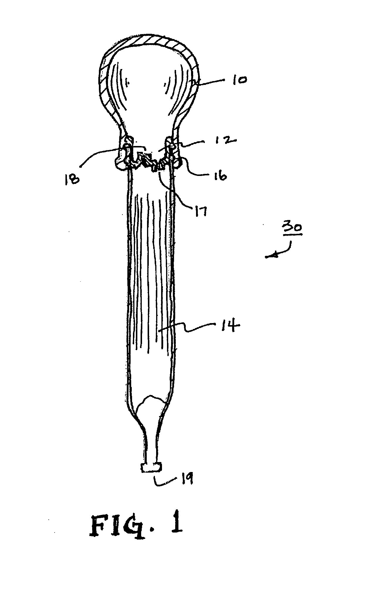
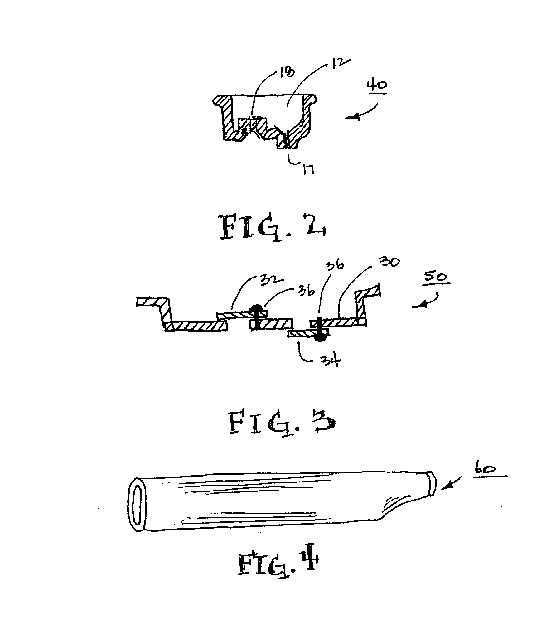
[0014]The present invention has three members, an elongated hollow body member, a means for filling or emptying the hollow body member, such as a squeeze bulb to draw fluid up into the elongated hollow body member, and a valve placed between the hollow body and the filling / emptying means. The addition of a valve at the top of the hollow tube before the bulb end, allows a baster to be held in various orientations with less fluid spillage than a prior art baster. The valve can be a valve assembly having two opposing valves which allow air to be expelled outward and also for air to be drawn inward. The use of a bi-directional check valve will mean that a positive pressure is necessary to force the liquid out of the tube. In addition, a vent can be provided so that the vent needs to be closed to draw a vacuum. While this creates an additional operation for the user to perform to use the baster it adds to the safety and reliability of the function.
[0015]The check valve assembly located at the top of the tube improves the seal and reduces the volume of air over the column of liquid, increasing the effectiveness of the baster to hold the liquid without leaking. By making the check valve assembly out of a single elastomeric element, it offers an economical solution to the current prior art.

Problems solved by technology

Commercially there have been few substantial improvements made to these devices due to the low cost nature of the device.
But, the low cost basters do not adequately contain the liquid so as to effectively reduce leakage of liquid or partial solids that are drawn into the device for transfer to the desired location.
Liquid and / or partial solids that are drawn up into the hollow member often leak out of the baster unintentionally.
Also if the elongated hollow body member is tilted at a sufficient angle it allows the liquid contents to break the vacuum, across the baster, causing the liquid to leak out of the elongated hollow body member.
Leaks can also occur because the heat from the liquids causes the pressure of the air to build up in the bulb and force out some of the liquid or because something inadvertently places pressure on the bulb, such as a weighted object or a person inadvertently putting a hand or leaning on the bulb.
The disadvantage of leaking is that the liquid or partial solids are hot enough to burn users or people and pets that are nearby.
Also the leaking contents can spill on the floor, the counter, or the stove creating an unsightly mess, or worse, a safety hazard because of slip-and-falls or because the oven's heating element can ignite the liquid creating a fire hazard.
In addition, over time the resilient bulb stiffens and becomes less resilient decreasing its ability to pull a vacuum and to hold liquids and partial solids in the elongated hollow body member.
The materials that are used are such that they deteriorate over time.
Frequently cracks develop in the bulb, which again affects the ability to create suction in the elongated hollow body member.
The deterioration can lead to inadequate sealing, which again causes problems with the baster holding vacuum.
The junction between the bulb and the elongated hollow body member also deteriorates over time as the resilient bulb ages, losing elasticity.
Many of the commercially available basters can be cleaned in dishwasher, but this can accelerate deterioration by assembling and disassembling the bulb and the elongated hollow body member.
Also, the heat of the dishwasher can cause the elastomeric bulb to outgas elastomers and / or plasticizers and lose resilience and the ability to seal with the hollow body.
Further, the prior art basters typically can not be tilted at an angle so as to be effective in easily and efficiently basting foods.
The basters which attempt to solve the problems note above present expensive solutions, and are not commercially cost effective.
For example, where the basters have a primary valve located at the open tapered end of the tube, they tend to not seal adequately, are difficult to clean, or are complex in design and / or in operation.
The problems with the prior art basters are seen in the prior art patents.
This presents sealing problems.
The slippery nature of the liquid being drawn into the tube will tend to prevent the ball from sealing.
Changing the angle and orientation of the baster tube will limit the effectiveness of the sealing.
This function required the “pumping” action of the bulb due to the volume of the baster being greater than the bulb and the diminished effectiveness of the bulb to create a vacuum due to the vent hole.
Due to the nature of an open hole in the top of the tube, the Porter baster does not appear to prevent liquids from coming into contact with the user and causing harm, if the baster is in a horizontal position.
Even though this feature is claimed there appears to be a lack of enough details to make them function.
Since the ball could not be removed for cleaning, it could be problematic in getting the dropper clean, and would appear to creates another loose part.

Method used


Image

  • Leak Resistant Siphoning Device For Use in Fluid Transfer
  • Leak Resistant Siphoning Device For Use in Fluid Transfer
  • Leak Resistant Siphoning Device For Use in Fluid Transfer

Examples


Embodiment Construction

[0035]The present invention has all the advantages of a prior art baster with several additional advantages. This invention draws on the principals of a vacuum and the addition of a valve at the top of the baster tube between the vacuum source and the tube to create a leak proof device that is simpler to operate, more dependable and as easy to clean than the prior art that is commercially available.

[0036]One configuration of the present invention is illustrated in FIG. 1. The present invention, as represented via the example of a baster, consists of a resilient bulb 10 and a hollow elongated tube 14. Stretching the open end of the bulb 10 over the end of the tube 14 easily assembles these parts. Circumferential projections 16 are added to the elongated tube 14 to increase the sealing properties between the bulb 10 and the tube 14.

[0037]Although the invention is illustrated as a baster, it should be appreciated that the present invention could be applied to any device used for fluid ...


PUM

PropertyMeasurementUnit
shapeaaaaaaaaaa
suctionaaaaaaaaaa
pressureaaaaaaaaaa

Abstract

An improved, leak resistant, siphoning device that includes an elongated hollow body member, a means for filling and emptying the hollow body member, such as an elastomeric resilient suction bulb and a valve placed between the hollow member and the filling / emptying means. The suction bulb defines a chamber therein, so that when it is squeezed and released it will create suction to direct fluid up through the first open head end into the elongated hollow body member using pressure differential. Squeezing the suction bulb can release the liquid and partial solids held within the elongated hollow body member out of the first open head end. The suction bulb also has an optional opening for venting heated air from the bulb, and a means to selectively close the opening for creating vacuum or pressure required to draw or expel liquid from the tube.

Description

BACKGROUND OF THE INVENTION[0001]The present invention relates to a siphoning and discharge device for use in fluid transfer. An example of such a device is a food baster. Other examples include medicine droppers and pipettes. More specifically the present invention relates to a leak resistant siphoning and discharge device for handling hot fluids, and which employs an elastomeric valve to prevent leakage.[0002]Basters are most commonly used in cooking to transfer hot juices from the bottom of the cooking pan back on to the meat / food being cooked in the pan to keep the meat / food moist while cooking. Commercially there have been few substantial improvements made to these devices due to the low cost nature of the device. But, the low cost basters do not adequately contain the liquid so as to effectively reduce leakage of liquid or partial solids that are drawn into the device for transfer to the desired location.[0003]Basters come in a variety of sizes and shapes. Basters typically co...

Claims


Application Information

Patent Timeline
Patent Type & Authority Applications(United States)
IPC IPC(8): A47J37/10
CPCA47J37/106A47J43/005
Inventor LOEWENTHAL, HOWARD LEESPRIEGEL, ANDREW RAYMOND
Owner SPRIEGEL ANDREW R
Learn More