Pedal Arrangement for a Motor Vehilce

a technology for pedals and motor vehicles, applied in the direction of propulsion unit arrangements, mechanical control devices, instruments, etc., can solve the problems of increased weight of pedals, increased cost and mounting costs, and inconvenient etc., and achieve the effect of simplifying the removal of e-gas modules on or from the brackets

Inactive Publication Date: 2008-08-28
ZF FRIEDRICHSHAFEN AG
View PDF16 Cites 4 Cited by
  • Summary
  • Abstract
  • Description
  • Claims
  • Application Information

AI Technical Summary

Benefits of technology

[0007]The object of the present invention is to perfect a pedal arrangement of the type mentioned in the introduction such that the mounting and optionally also the removal of the E-gas module on or from the bracket is simplified.
[0011]The E-gas module is fastened to the bracket preferably detachably via the plug-in connection and can be separated from the bracket as a structural unit, especially together with the gas pedal. However, the plug-in connection may at the same time form a clamped connection, which fixes the E-gas module on the bracket in a non-positive manner in addition to the positive-locking plug-in connection, in order to prevent the E-gas module from accidentally separating from the bracket. However, it is also possible, as an alternative or in addition to the clamped connection, to secure the E-gas module at the bracket by means of a snap-in connection, which is preferably designed as a detachable snap-in connection.
[0013]If the pedal arrangement is installed in a motor vehicle, the first holding groove extends especially from “top” to “bottom,” and the first foot or the E-gas module is preferably plugged or pushed in from “top” to “bottom.” Furthermore, in the mounted state, the E-gas module may be in contact with a stop, which limits a further displacement of the first foot or of the E-gas module, especially “downwardly.” The mounting direction pointing “downwardly” represents a certain self-securing for the E-gas module, so that the latter cannot become separated from the bracket by itself or due to vibrations. The terms “top” and “bottom” shall be seen here in connection with the gravitational field of the earth. The intrinsic weight of the E-gas module thus ensures the firm cohesion of the E-gas module and the bracket, and this cohesion can be supplementarily enhanced by means of the snap-in connection, which is additionally possible.
[0023]In particular, the following advantages can be achieved with the pedal arrangement according to the present invention:
[0027]Cost saving due to simple mounting and the possible elimination of fastening elements.

Problems solved by technology

The prior-art fastenings of E-gas modules are, however, cost- and mounting-intensive, because three fastening points are usually provided with bushings, screws and / or nuts.
Furthermore, these components cause extra costs because of the logistics associated therewith.
Furthermore, these components may contribute to the overall weight of the pedal arrangement to a rather substantial extent.
Finally, the metallic components (screws, bushings, nuts) are to be removed in case of reuse, which increases the effort and hence the costs for reuse.

Method used


Image

  • Pedal Arrangement for a Motor Vehilce
  • Pedal Arrangement for a Motor Vehilce
  • Pedal Arrangement for a Motor Vehilce

Examples


Embodiment Construction

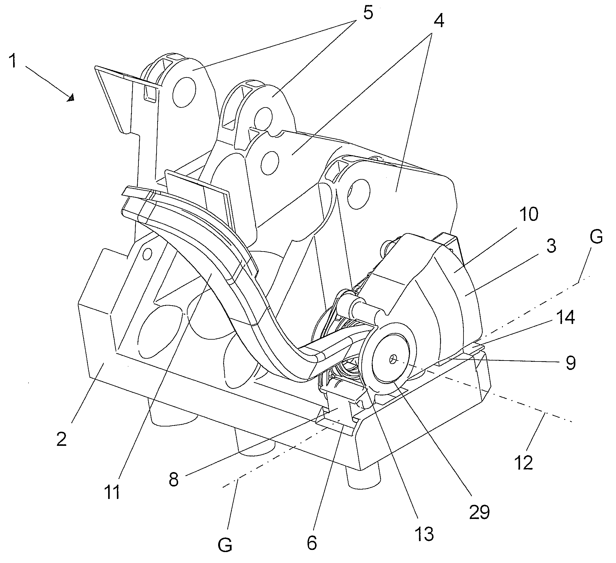
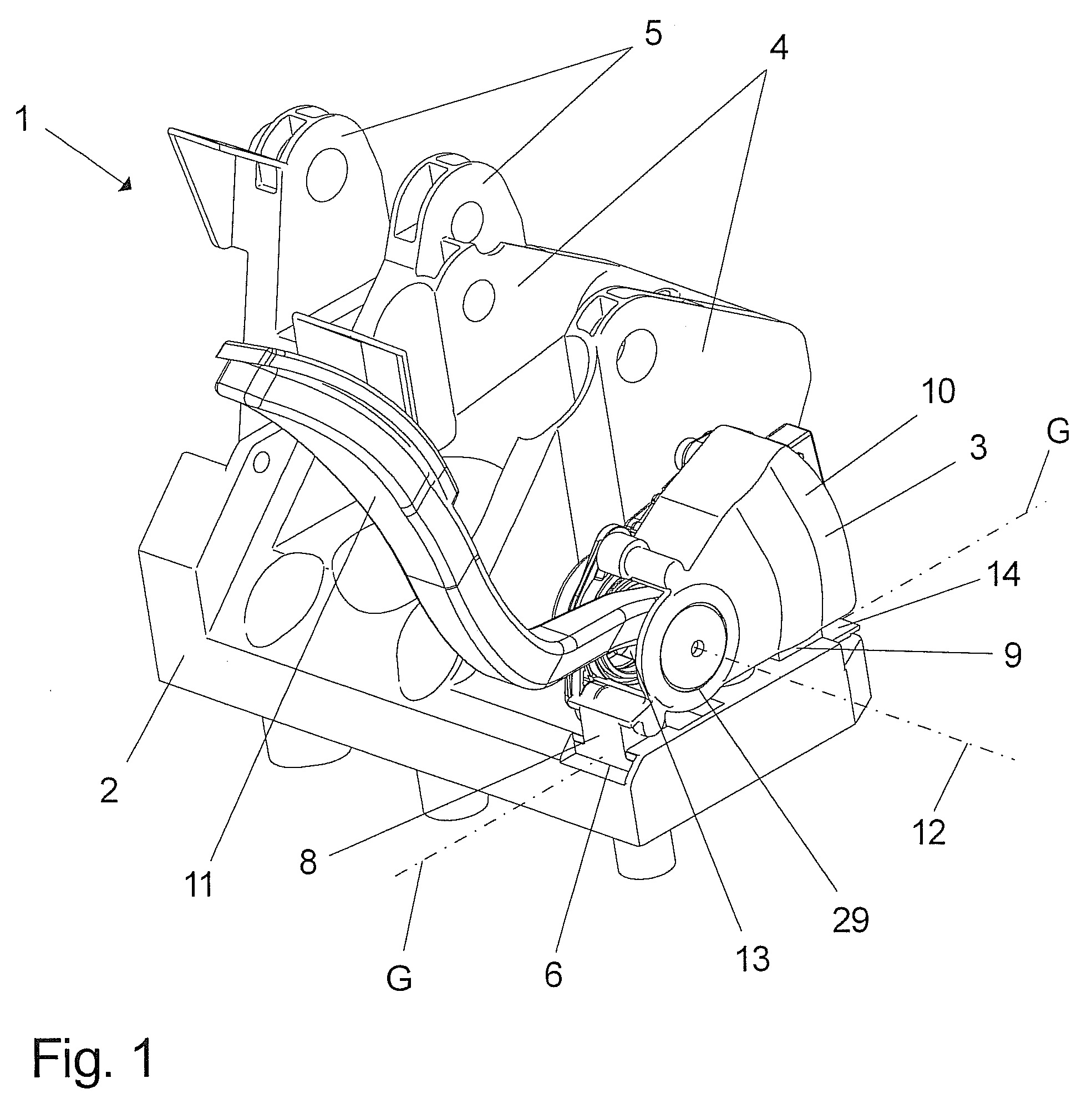
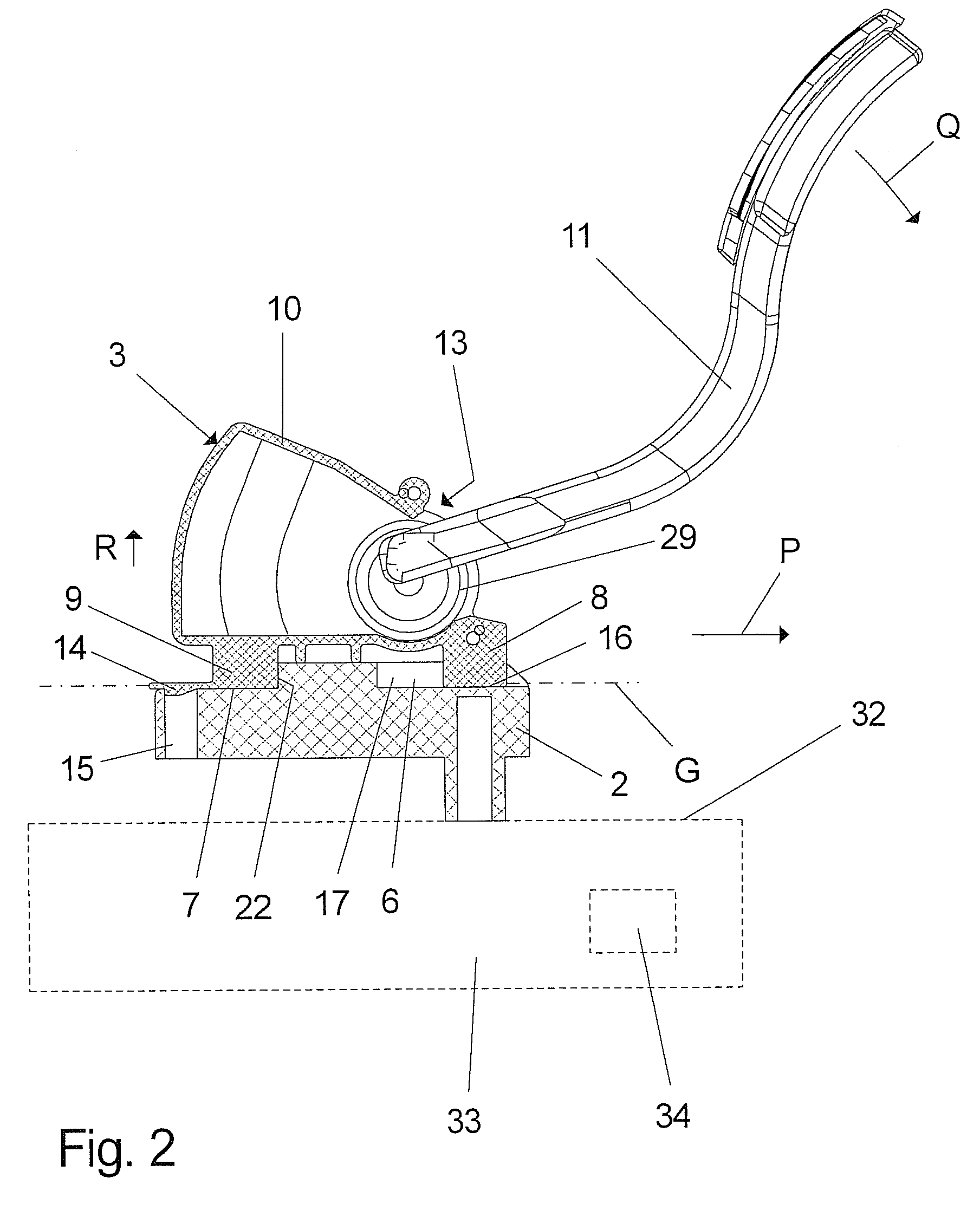
[0040]Referring to the drawings in particular, FIG. 1 shows a perspective view of an embodiment of the pedal arrangement 1 according to the present invention, in which an E-gas module 3 is fastened to a pedal block (bracket) 2. The pedal block 2 is used as a bracket for the E-gas module 3 and is provided, furthermore, with mounts 4 and 5 for a brake pedal, not shown, and a clutch pedal, likewise not shown. In an automatic variant of the pedal arrangement, which is not shown here, the mount 5 for the clutch pedal may, of course, be eliminated. The pedal block 2 is manufactured as a one-piece injection molding consisting of a plastic and has two holding grooves 6 and 7 (see FIG. 2), which are meshed with by two feet 8 and 9 provided at the E-gas module 3. The E-gas module 3 is provided with a housing 10, which is manufactured from a plastic and with which the feet 8 and 9 are made in one piece. Furthermore, a gas pedal 11 is mounted at a pedal bearing 29 in such a way that it is pivot...


PUM


Abstract

A pedal arrangement is provided for a motor vehicle with a bracket (2) and with an E-gas module (3) fastened thereto via a plug-in connection. The an E-gas module (3) has a pedal bearing (29), on which a gas pedal (11) is mounted pivotably about a pivot axis (12), wherein a structural unit that is independent from the bracket (2) is formed by the E-gas module (3).

Description

CROSS REFERENCE TO RELATED APPLICATIONS[0001]This application is a United States National Phase application of International Application PCT / DE 2006 / 001020 and claims the benefit of priority under 35 U.S.C. § 119 of German Patent Application DE 10 2005 028 514.7 filed Jun. 17, 2005, the entire contents of which are incorporated herein by reference.FIELD OF THE INVENTION[0002]The present invention pertains to a pedal arrangement for a motor vehicle, with a bracket and with an E-gas module fastened to same via a plug-in connection with a pedal bearing, at which a gas pedal is mounted pivotably about a pivot axis.BACKGROUND OF THE INVENTION[0003]Prior-art E-gas modules are connected, e.g., by screw connections (mostly three) to the vehicle body or the pedal block. It is possible as a result to mount and remove these E-gas modules as often as desired. In addition, a fastening is embodied that makes possible the force transmission to the vehicle body or the pedal block without problems. ...

Claims


Application Information

Patent Timeline
Patent Type & Authority Applications(United States)
IPC IPC(8): B60K26/00G05G1/30
CPCB60K26/02Y10T74/20888Y10T74/20534B60K26/00
Inventor BURGSTALER, ANDREEDUTZ, JANMEYER, WOLFGANGHULSMANN, SILKE
Owner ZF FRIEDRICHSHAFEN AG
Why Eureka
Try Eureka