
Manufacturing method for an LED light string and a jig for making the LED light string

a manufacturing method and led light technology, applied in the manufacture of electrode systems, light and heating apparatuses, electric discharge tubes/lamps, etc., can solve the problems of difficult assembly, more susceptible to mistakes, and difficulty in manufacturing, and achieve the effect of effective completion of the final produ

Inactive Publication Date: 2008-08-21
REAL BONUS
View PDF2 Cites 16 Cited by
  • Summary
  • Abstract
  • Description
  • Claims
  • Application Information

AI Technical Summary

Benefits of technology

"The present invention provides a method for manufacturing an LED light string with a smart position apparatus that can complete a final product in a limited space. The method includes winding electrical wires in a jig with spiral grooves, removing portions of the wires to provide exposed segments, and placing LED chips on the exposed segments. The LED chips are connected to the wires by connectors, and the wires are sealed. The invention also provides a jig for attaching LED chips to electrical wires, a cutting tool for removing insulation from the wires, and an assembly for manufacturing the LED light string. The technical effects of the invention include efficient and high-quality production of LED light strings in limited space, improved positioning of LED chips, and simplified manufacturing process."

Problems solved by technology

Since the traditional LED must be directionally connected, it causes difficulty in assembling and is more susceptible to mistakes.
Although the above LED light string provides an effective structure, there is still some difficulty in manufacturing.
Because of this arrangement, the assembly requires a large workspace.
In addition, it is difficult to place each interval accurately and as a result the manufacturing speed is slower than desired.

Method used


Image

  • Manufacturing method for an LED light string and a jig for making the LED light string
  • Manufacturing method for an LED light string and a jig for making the LED light string
  • Manufacturing method for an LED light string and a jig for making the LED light string

Examples


Embodiment Construction

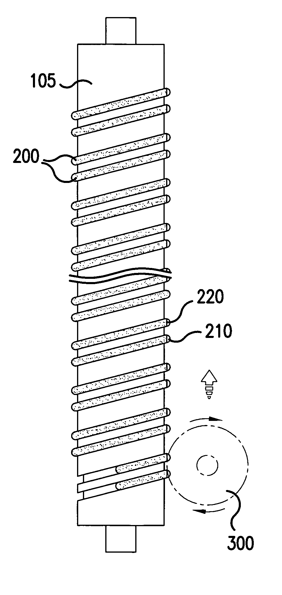
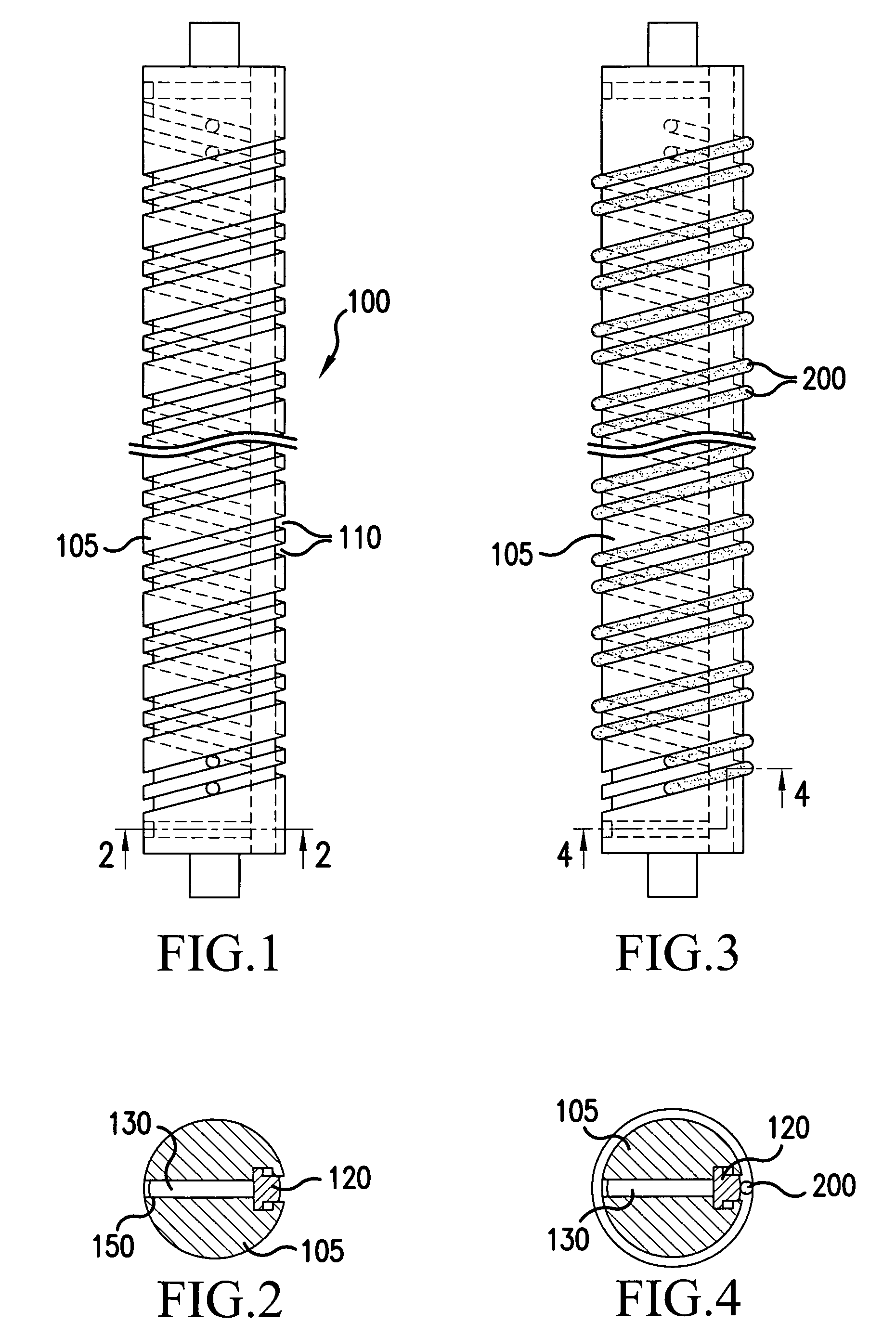
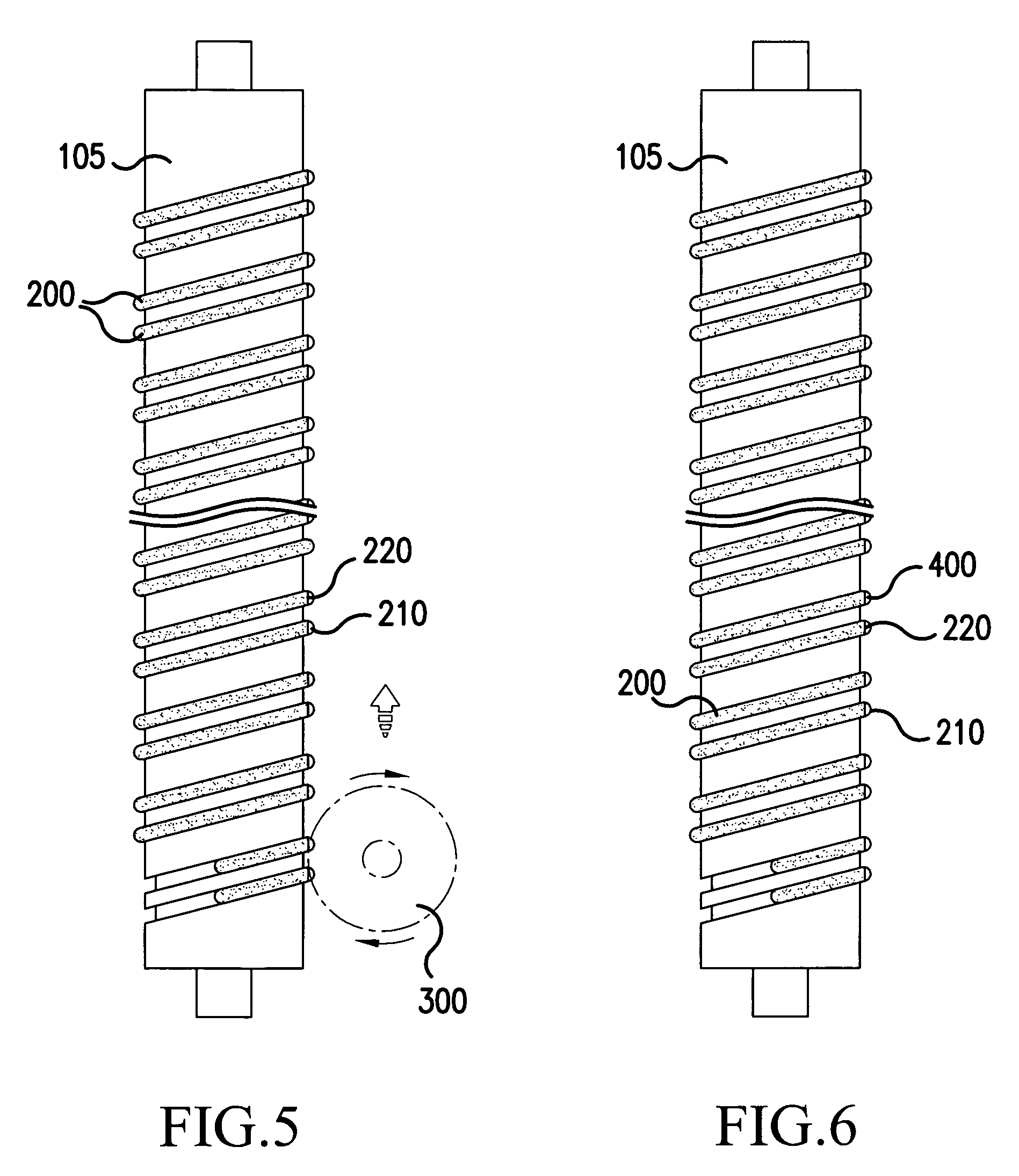
[0040]A first exemplary manufacturing method and associated jig will be described with respect to FIGS. 1-8 and 10. Specifically, as shown in FIG. 10, the method of manufacturing an LED light string includes providing a jig having a main body and spiral grooves thereon (S1100); winding electrical wires around the body (S1200); cutting away portions of the electrical wires to expose segments of the conductive cores (S1300); placing an LED chip on each of the exposed segments associated with one of the electrical wires (S1400); drying the LED chip / electrical wire combination (S1500); welding connectors to electrically connect the LED chips with corresponding exposed segments of the other electrical wire (S1600); covering the LED chips and connectors with a package to seal the LED chips and the metal wires respectively to form a plurality of lighting units on an LED light string (S1700); and drying the packages (S1800).

[0041]In order to explain the manufacturing procedures of the prese...


PUM


Abstract

A method of manufacturing an LED light string using a jig having a main body and a plurality of spiral grooves formed thereon adjacent to each other is provided. The method includes winding an electrical wire in each of the grooves, removing portions of the electrical wires to provide a plurality of spaced exposed segments at successive locations on each of the electrical wires, placing LED chips on at least some of the plurality of exposed segments formed in one of the electrical wires, connecting each LED chip to a corresponding exposed segment on a different electrical wire by a connector, and sealing each LED chip and connector. A jig for attaching one or more LED chips to a plurality of electrical wires is also provided.

Description

CROSS REFERENCE TO RELATED APPLICATIONS[0001]This application claims priority to Taiwanese Patent Application No. 96102761, filed Jan. 25, 2007, and is herein incorporated by reference in its entirety.BACKGROUND OF THE INVENTION[0002]1. Field of the Invention[0003]The present invention generally relates to a method of manufacturing a light-emitting diode (LED) light string and jig for making the LED light string. More particularly, the present invention relates to a method of manufacturing the LED light string using a jig having a main body and a plurality of grooves formed thereon and the jig having the main body and the plurality of grooves formed thereon.[0004]2. Description of Related Art[0005]A traditional LED light string usually includes at least two electrical wires connected with a plurality of LEDs, each LED always has a pair of conductive legs for connecting the LED to the corresponding wires. Since the traditional LED must be directionally connected, it causes difficulty...

Claims


Application Information

Patent Timeline
Patent Type & Authority Applications(United States)
IPC IPC(8): H01J9/02H01J9/46
CPCF21S4/001F21Y2101/02H01L33/62H01L2224/48091H01L2924/00014F21S4/10F21Y2115/10
Inventor TSAI, KENNETH
Owner REAL BONUS
Learn More