
Device for Coupling Electromagnetic Radiation from a Source into a Microwave Chamber

Inactive Publication Date: 2008-08-21
TEXAS INSTR INC
View PDF6 Cites 5 Cited by
  • Summary
  • Abstract
  • Description
  • Claims
  • Application Information

AI Technical Summary

Benefits of technology

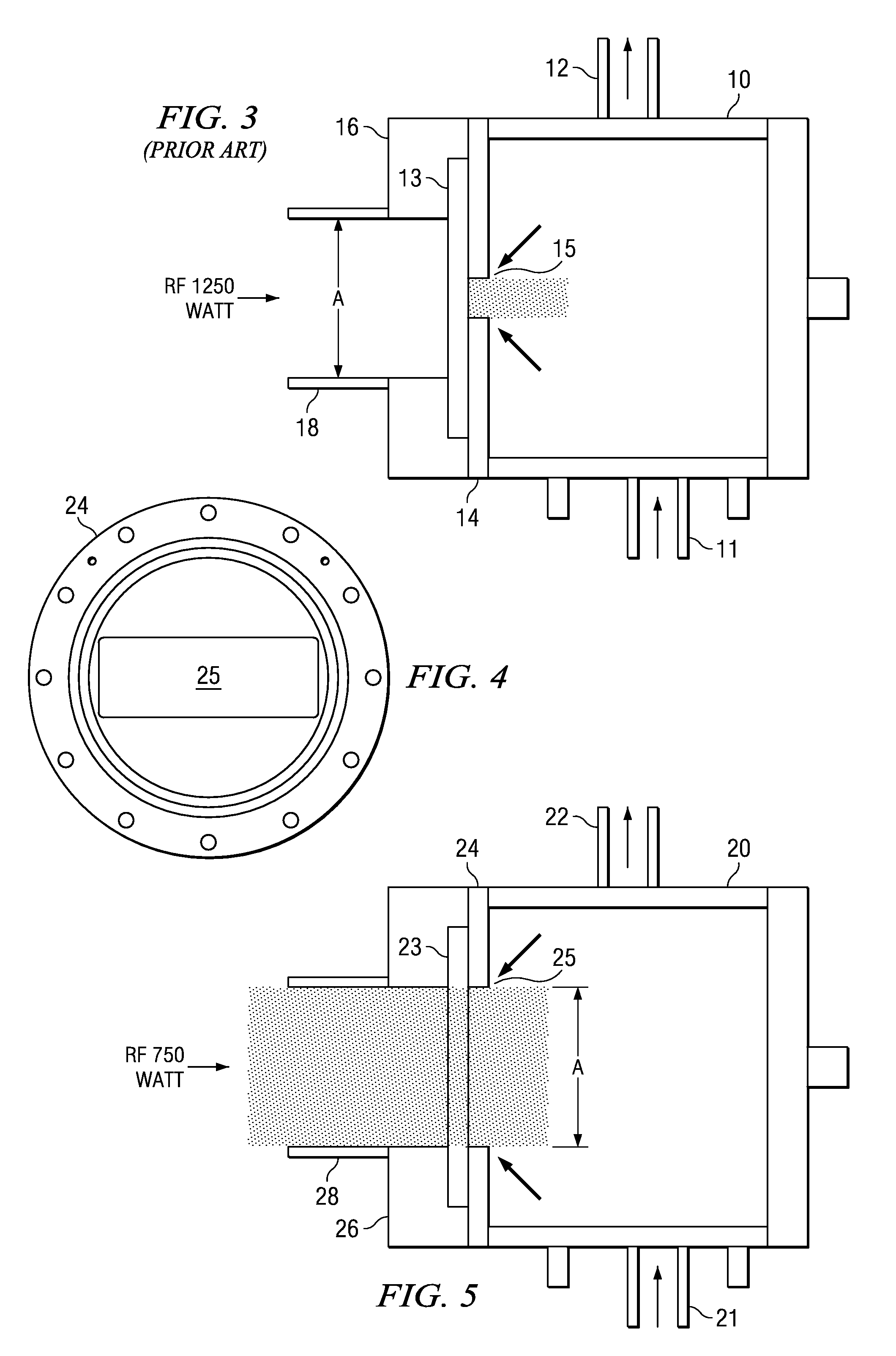
[0010]The present invention has been devised with the foregoing in mind. Thus the present invention provides a device for coupling electromagnetic radiation from a source into a microwave chamber. The device comprises a waveguide and is configured to be attached to a window of the microwave chamber. The device also comprises a shield operable to cover an outer part of the window so as to prevent electromagnetic radiation passing through the outer part of the window covered by the shield. The shield defines an opening configured to expose an inner part of the window in such a manner as to allow electromagnetic radiation to pass through the inner part of the window. The inner part of the window refers to a generally central portion of the window and the outer part of the window refers to a generally peripheral part of the window. The opening has a cross-sectional area substantially equal to the cross-sectional area of the waveguide. In this way, burning of the glass window by the microwave radiation is substantially eliminated.
[0012]It is surprising that providing an opening into the chamber that has the same cross-sectional area of the waveguide does not cause any of the RF radiation coupled into the chamber to be reflected back out again. As stated above, the chamber is comparable to a resonator cavity and it has always been known in the art that RF radiation will be reflected out of a cavity if it is introduced into the cavity through an aperture any larger than a very small slit or hole. However, surprisingly, the RF radiation stays in the chamber to react with the gases introduced into the chamber so as to form a plasma. Even more surprisingly, lower power RF radiation can be coupled into the chamber when an area of the window is exposed that has the same cross-sectional area as the waveguide. It would be expected that, due to the reflective properties of the chamber, a higher power of radiation would need to be coupled into the chamber to prevent it being reflected back through the larger aperture in the window.

Problems solved by technology

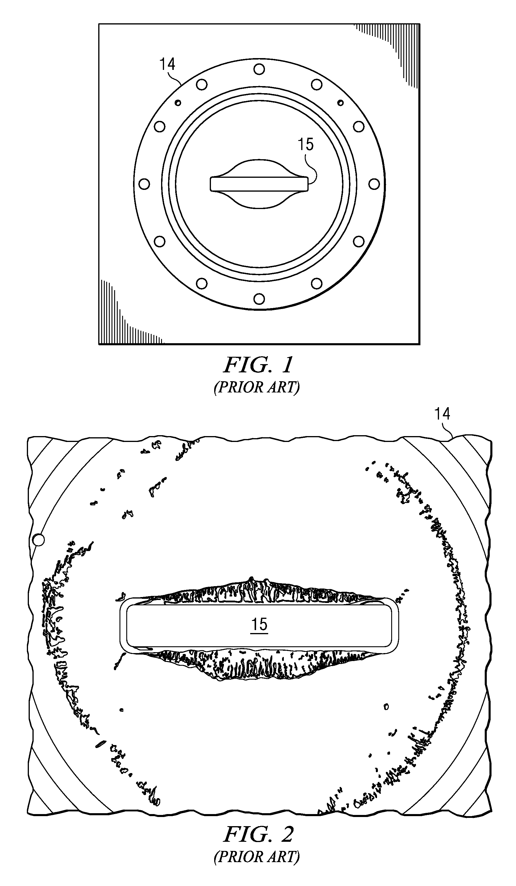
Furthermore, when the glass in the window (13) is burned, this results in particles being formed, which become dislodged from the glass surface on the inside of the chamber and can cause contamination of the gas that flows into the process chamber during the tungsten deposition process.
This means that the intensity of the radiation that has to be used is such that it eventually will cause burning of the glass in the window (13).

Method used


Image

  • Device for Coupling Electromagnetic Radiation from a Source into a Microwave Chamber
  • Device for Coupling Electromagnetic Radiation from a Source into a Microwave Chamber
  • Device for Coupling Electromagnetic Radiation from a Source into a Microwave Chamber

Examples


Embodiment Construction

[0019]Referring now to FIG. 4 and FIG. 5, a microwave chamber (20) has an inlet pipe (21), which is connected to the chamber (20) in a bottom surface of the chamber (20) and is operable to allow gases to enter the chamber (20). An outlet pipe (22) is connected to the chamber (20) in a top surface of the chamber and is operable to allow gases to exit the chamber (20). The outlet pipe (22) is connected to a process chamber (not shown), in which semiconductor wafers are to be processed.

[0020]A window (23) is provided on a front face of the chamber 20. An outer aluminum plate (26) facing outwardly of the front face of the chamber (20) secures the window (23) to the front face of the chamber (20) and is operable to provide a vacuum seal so that the chamber (20) is airtight once it has been pumped down to a required pressure. The aluminum plate (26) defines an opening, which acts as a waveguide (26). The waveguide (26) has a cross-sectional area (29) and is operable to allow microwave rad...


PUM

PropertyMeasurementUnit
Thicknessaaaaaaaaaa
Areaaaaaaaaaaa
Electromagnetismaaaaaaaaaa

Abstract

A device for coupling electromagnetic radiation from a source into a microwave chamber (20) is configured to be attached to a window (23) of the microwave chamber (20). The device comprises a waveguide (26) and a shield operable to cover an outer part of the window (23) in such a manner as to prevent electromagnetic radiation passing through the outer part. The shield defines an opening (25) configured to expose an inner part of the window (23) in such a manner as to allow electromagnetic radiation to pass through the inner part from the waveguide (26). The opening (25) has a cross-sectional area substantially equal to the cross-sectional area of the waveguide (26).

Description

FIELD OF THE INVENTION[0001]The present invention generally relates to a device for coupling electromagnetic radiation from a source into a microwave chamber. More particularly, the present invention relates to a device for attachment to the window of a microwave chamber for guiding microwaves into the microwave chamber.BACKGROUND OF THE INVENTION[0002]Plasma-enhanced chemical vapor deposition (PECVD) is used in semiconductor processing to deposit electrodes on integrated circuits as high quality metallic thin films. The electrode material, for example tungsten, must be deposited on the integrated circuit in a plasma chamber in a clean environment. A plasma is created by allowing streams of gases to flow into a vacuum chamber—one gas comprising the metal that it is required to deposit and the other gases being reactant gases. The plasma chamber (process chamber) needs to be cleaned with “clean gas”. Clean gas is produced by exposing NF3 gas to microwave radiation in a cavity (microw...

Claims


Application Information

Patent Timeline
IPC IPC(8): H05K13/04
CPCC23C16/4405H05B6/708Y10T29/5313H05B6/806Y10T29/53174H05B6/76
Inventor BRUECKL, MARKUSPFEIFFER, WOLFGANGZWACK, THOMASHOETTE, ALEXANDERGRUEMBEL, PETER
Owner TEXAS INSTR INC
Learn More