
Flexible Bathtub Waste Pipe Assembly for Bathtubs and the Like

a waste pipe and bathtub technology, applied in the direction of pipes, water installations, constructions, etc., can solve the problems of inconvenient installation of bathtubs, and inconvenient maintenance, etc., to achieve convenient installation, improve the chance of leakage, and improve the effect of leakage prevention

Inactive Publication Date: 2008-08-21
WCM IND INC
View PDF99 Cites 57 Cited by
  • Summary
  • Abstract
  • Description
  • Claims
  • Application Information

AI Technical Summary

Benefits of technology

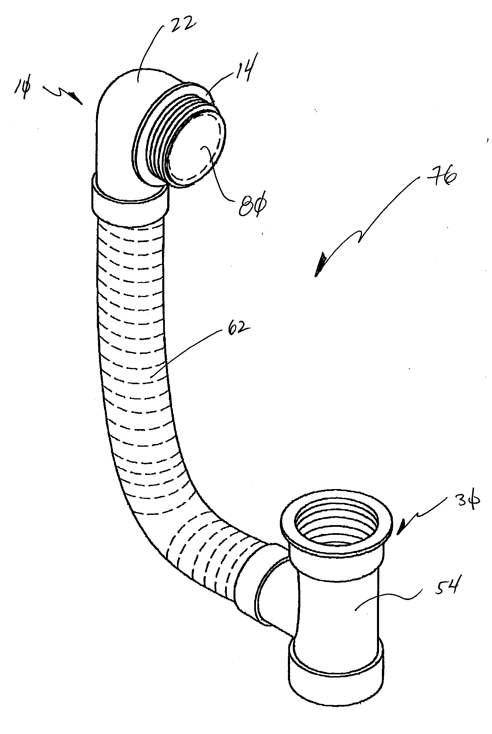
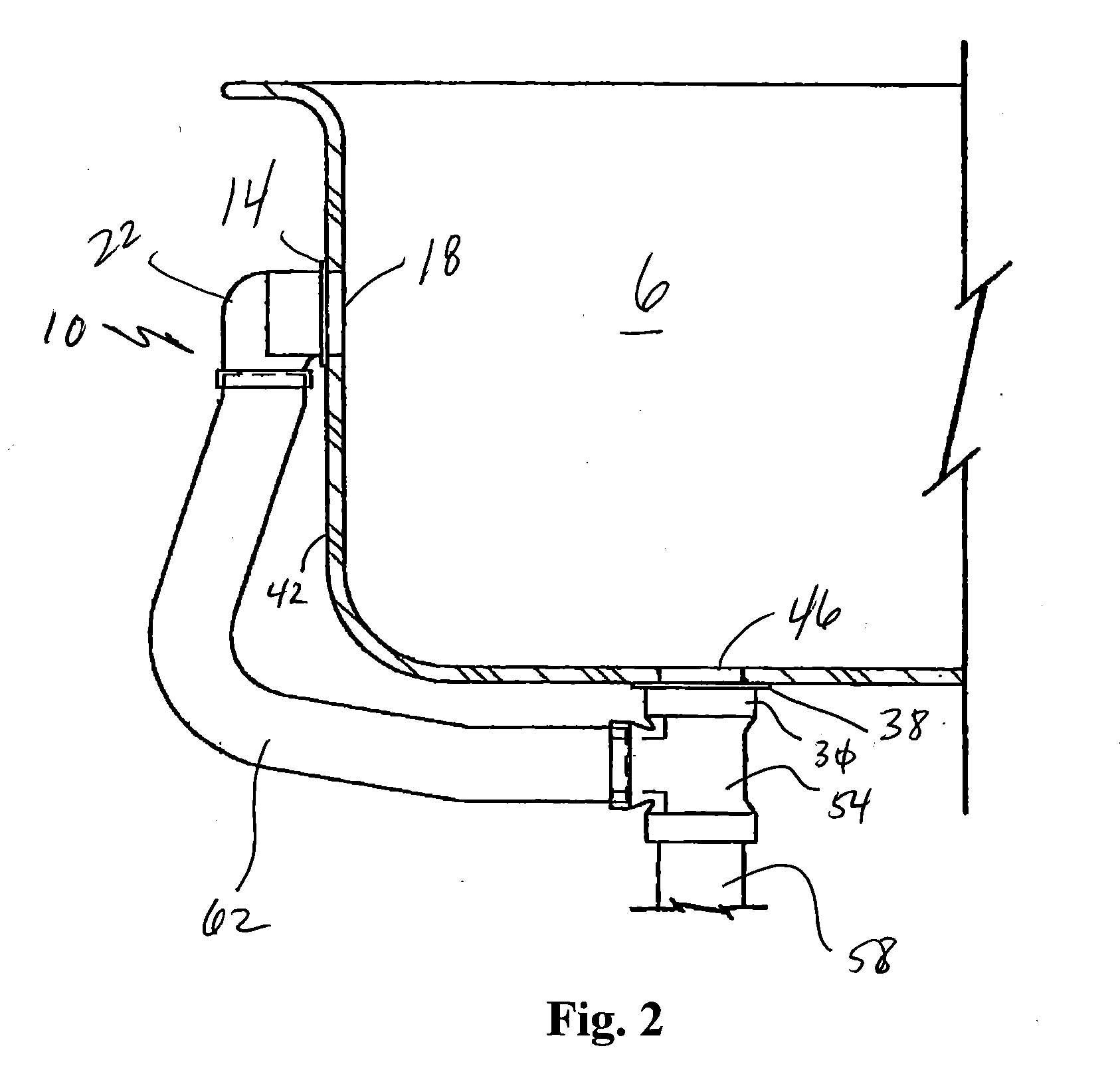
[0008]It is another aspect of the present invention to provide a system and method that can be selectively customized during installation. More specifically, it is contemplated that the flexible portions of the pipes described herein may be cut to length as needed. Often, as one skilled in the art will appreciate, plumbing systems are not perfectly aligned with the overflow and / or drain ports of a bathtub. In the past, a plumbing contractor would be required to alter the plumbing system to account for the misalignment, an expensive and time consuming undertaking. Alternatively, expensive modifications related to the installation of the bathtub, sink, etc. would have to be performed. Some plumbing contractors simply exert undesired force to move parts into alignment, which stresses the rigid pipes and makes them susceptible to leaking, breakage, etc. Thus, embodiments of the present invention provide a system wherein flexible pipes are provided that may be adjusted to a preferred size (e.g. by cutting) and selectively bent to accommodate misalignments. This aspect of the present invention is desirable because the addition of multiple elbows is not required. The addition of multiple elbows not only increases the chances for leaks, but also creates a complicated flow path for drainage water that can add to the instances of clogging. As will be apparent to one skilled in the art, the robustness offered by the present invention enables vertical and / or horizontal adjustments in a superior manner, as compared to prior art systems and methods.
[0009]Yet another aspect of the present invention is to provide a system and method that can be installed on virtually any type of bathtub. More specifically, the horizontal and / or vertical distances between the drain port and the overflow port can vary from bathtub to bathtub. The robustness provided by the flexible overflow and / or drain pipes of the present invention, and the ability to customize the same, allows for desired accommodation for bathtubs of various type / design. Thus, contractors no longer need to customize a plurality of rigid tubes since embodiments of the present invention allow for easy cutting and modifying of flexible tubes to meet their requirements.

Problems solved by technology

Often, as one skilled in the art will appreciate, plumbing systems are not perfectly aligned with the overflow and / or drain ports of a bathtub.
In the past, a plumbing contractor would be required to alter the plumbing system to account for the misalignment, an expensive and time consuming undertaking.
Alternatively, expensive modifications related to the installation of the bathtub, sink, etc. would have to be performed.
Some plumbing contractors simply exert undesired force to move parts into alignment, which stresses the rigid pipes and makes them susceptible to leaking, breakage, etc.
The addition of multiple elbows not only increases the chances for leaks, but also creates a complicated flow path for drainage water that can add to the instances of clogging.

Method used


Image

  • Flexible Bathtub Waste Pipe Assembly for Bathtubs and the Like
  • Flexible Bathtub Waste Pipe Assembly for Bathtubs and the Like
  • Flexible Bathtub Waste Pipe Assembly for Bathtubs and the Like

Examples


Embodiment Construction

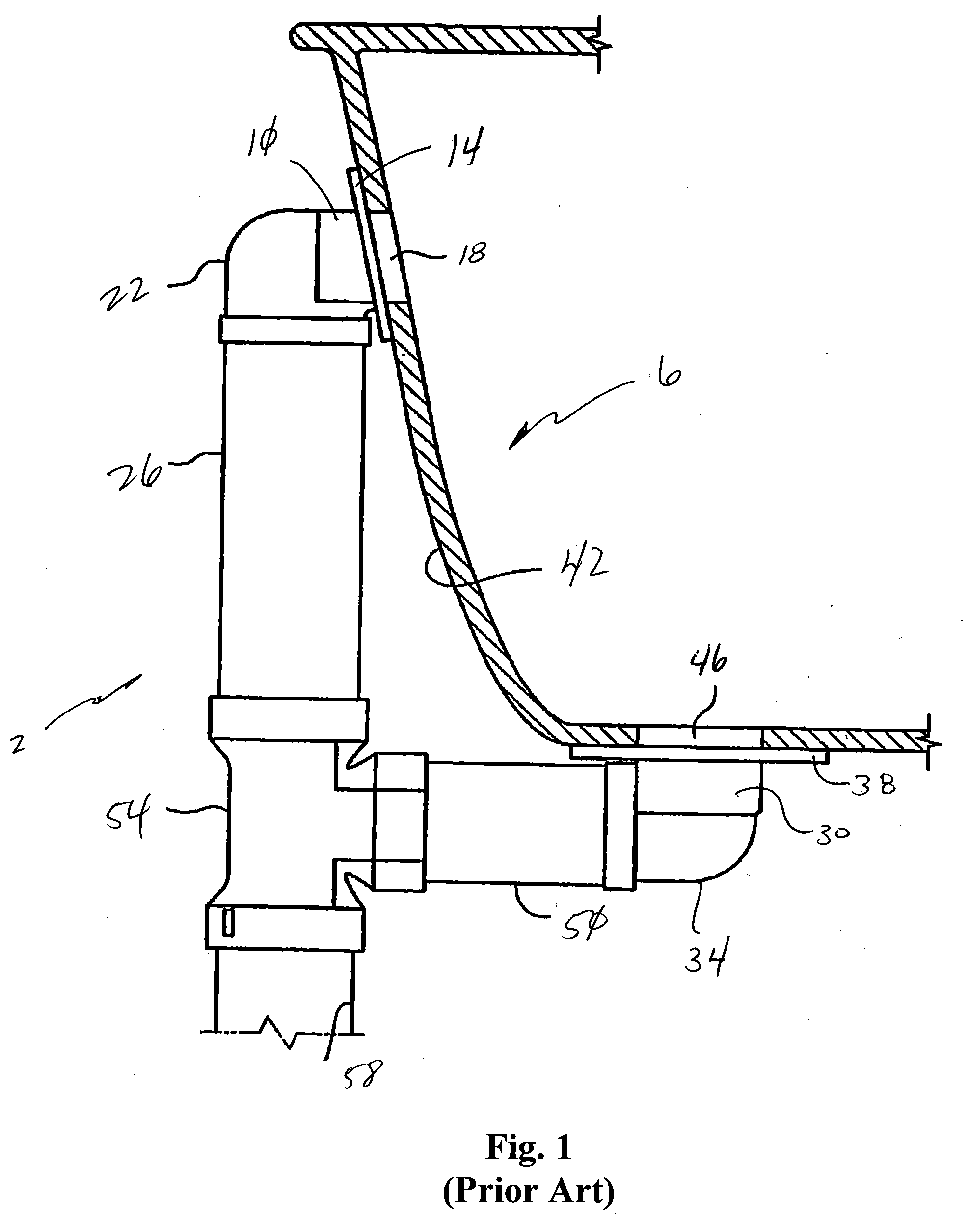
[0024]Referring now to FIG. 1, a prior art method of interconnecting a plumbing system 2 to a bathtub 6 is shown. Here, an overflow assembly 10 having a flange 14 is shown interconnected to the bathtub 6 and placed in fluidic communication with an overflow port 18 of the bathtub 6. The overflow assembly 10 includes an overflow pipe 22 that is interconnected to a rigid vertical pipe 26. Similarly, the drain assembly 30, which includes a drain elbow 34 with a flange 38 that places the drain assembly 30 adjacent to the outer surface 42 of the bathtub 6, is placed in fluidic communication with a drainport 46 of a bathtub 6. The drain assembly 30 is interconnected to a rigid horizontal pipe 50. The rigid vertical pipe 26 and the rigid horizontal pipe 50 are interconnected to a tee connector 54 that is also interconnected to a main drain pipe 58 of the plumbing system 2. As it will be appreciated by those skilled in the art upon review of FIG. 1, vertical and horizontal misalignments para...


PUM


Abstract

A bathtub waste pipe assembly for draining fluid from a bathtub where the bathtub has an upper overflow drain and a lower drain. The bathtub waste pipe assembly includes a flexible hollow pipe extending from the upper overflow drain to the lower drain.

Description

[0001]This application is a Continuation-In-Part of pending U.S. patent application Ser. No. 10 / 971,895, filed Oct. 22, 2004, the entire disclosure of which is incorporated by reference herein.[0002]This application is also related to U.S. patent application Ser. No. 10 / 732,726, filed Dec. 10, 2003, U.S. Patent Application Publication No. 2004 / 0117907, which is a Continuation-In-Part of U.S. patent application Ser. No. 09 / 954,420, now U.S. Pat. No. 6,691,411, filed Sep. 17, 2001 and a Continuation-In-Part of U.S. patent application Ser. No. 10 / 229,533, now U.S. Pat. No. 6,675,406, filed Aug. 28, 2002, the latter being a Continuation of abandoned U.S. patent application Ser. No. 09 / 953,724, filed Jun. 13, 2000, the entire disclosures of which are incorporated by reference herein.[0003]This application is also related to U.S. patent application Ser. No. 10 / 674,862, U.S. Patent Application Publication No. 2004 / 0068793, filed Sep. 30, 2003, which is a Continuation-In-Part of U.S. patent...

Claims


Application Information

Patent Timeline
IPC IPC(8): E03C1/24F16L11/00
CPCE03C1/232
Inventor BALL, WILLIAM T.
Owner WCM IND INC
Learn More