Wireless Receiving Apparatus, Wireless Transmitting Apparatus, and Interference Signal Removing Method
a technology of wireless transmission and interference signal, applied in the direction of amplitude demodulation, line-fault/interference reduction, baseband system details, etc., can solve the problems of transmission performance deterioration and not negligible, and achieve the effect of efficiently cancelling interference signals in multi-carrier communication
- Summary
- Abstract
- Description
- Claims
- Application Information
AI Technical Summary
Benefits of technology
Problems solved by technology
Method used
Image

Examples
embodiment 1
[0056]FIG. 5 shows a configuration of a radio communication base station apparatus (referred to as a “base station”) 100 according to the present embodiment. Further, FIG. 6 shows a configuration of mobile station 200 according to the present embodiment.
[0057]In base station 100 shown in FIG. 5, coding section 101 encodes transmission data (bit sequence) and outputs encoded transmission data to modulating section 102.
[0058]Modulation section 102 modulates the encoded bit sequence, generates a symbol and outputs the symbol to repetition section 103.
[0059]Repetition section 103 repeats the input symbol (referred to as “repetition”) and generates a plurality of same symbols. For example, when the repetition factor (RF) is four (RF=4), repetition section 103 obtains the four same symbols per symbol inputted from modulation section 102. In addition, here, sixteen symbols, S1 to S16, are subjected to repetition with the RF of 4 (RF=4) In other words, repetition section 103 obtains four sy...
embodiment 2
[0078]FIG. 8 shows a configuration of base station 300 according to the present embodiment. Base station 300 further has interleaver 301 in the configuration of base station 100 (FIG. 5) according to Embodiment 1.
[0079]Here, when symbols are subjected to repetition as in Embodiment 1, the plurality of same symbols subjected to repetition may be interleaved the frequency domain so that it is possible to improve the diversity effect in the frequency domain. Further, the plurality of same symbols subjected to repetition may be interleaved in the time domain so that it is possible to enhance the diversity effect in the time domain.
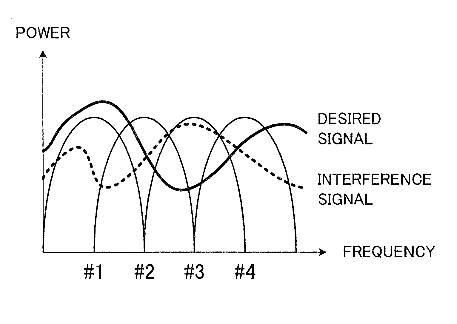
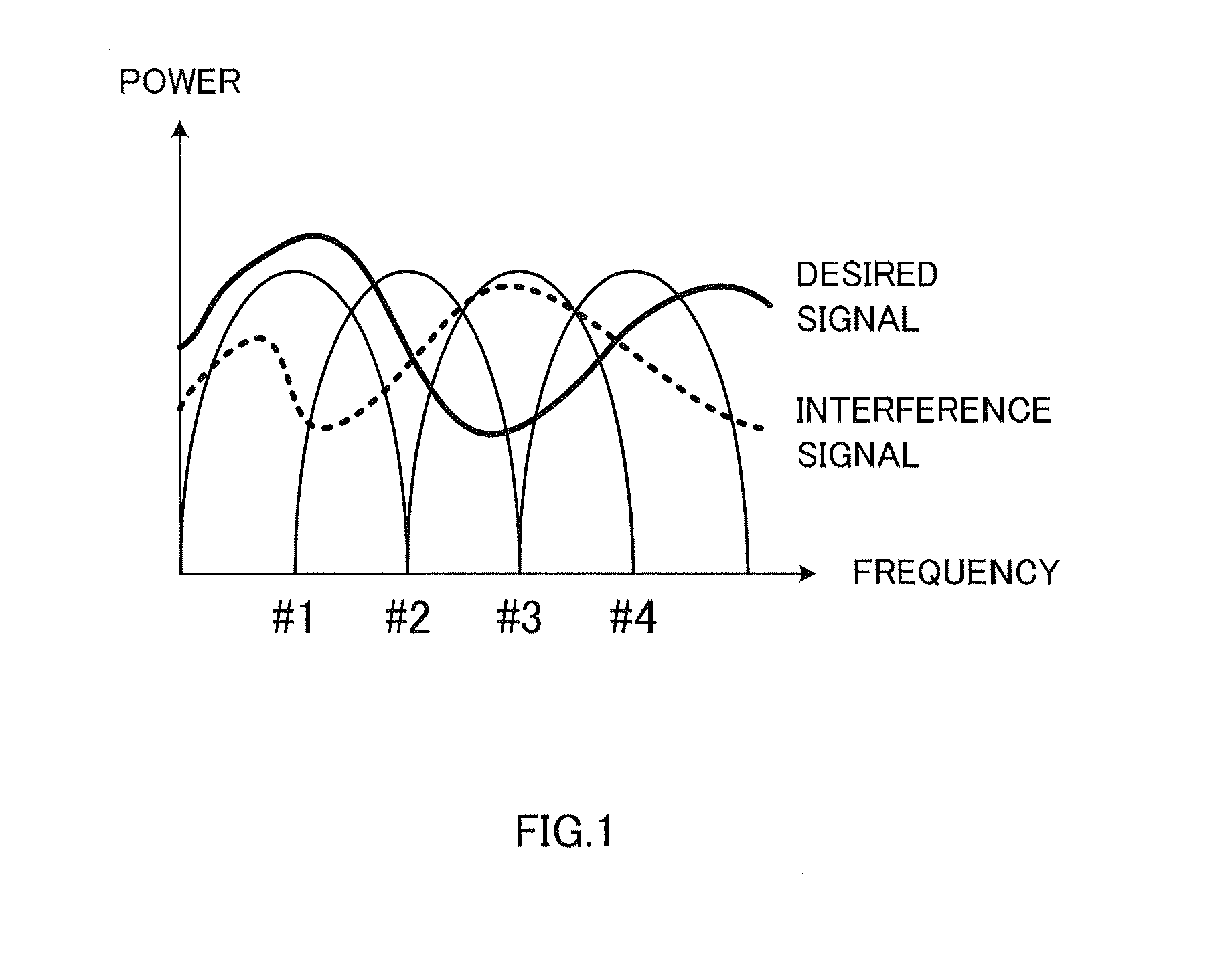
[0080]However, the mapping pattern of desired signals subjected to repetition onto subcarriers and a mapping pattern of interference signals subjected to repetition onto subcarriers needs to be the same in the frequency domain so that it is possible to obtain a desired signal by canceling interference signals from a received signal in mobile station 200 accord...
embodiment 3
[0086]Mobile station 200 according to Embodiment 1 increases the processing amount of matrix operation in MMSE processing, as the RF (Repetition Factor) increases. Therefore, in the present embodiment, MMSE processing is divided and performed.
[0087]FIG. 11 shows a configuration of mobile station 400 according to the present embodiment. In addition, in FIG. 11, the same components as mobile station 200 (FIG. 6) according to Embodiment 1 are assigned the same reference numerals and are not described. Further, in FIG. 11, the internal configuration of interference cancellation sections 403-1 to 403-3 is the same as the internal configuration of interference cancellation section 213 in FIG. 6.
[0088]In case of OFDM symbols at the beginning of the frame in FIG. 7, selecting section 401 outputs the pilot symbols mapped onto subcarriers #1 to #8 to channel estimating section 402. Further, selecting section 401 selects the plurality of same symbols according to the mapping pattern at the tim...
PUM
 Abstract
Description
Claims
Application Information
 - R&D
- Intellectual Property
- Life Sciences
- Materials
- Tech Scout
- Unparalleled Data Quality
- Higher Quality Content
- 60% Fewer Hallucinations
Browse by: Latest US Patents, China's latest patents, Technical Efficacy Thesaurus, Application Domain, Technology Topic, Popular Technical Reports.
© 2025 PatSnap. All rights reserved.Legal|Privacy policy|Modern Slavery Act Transparency Statement|Sitemap|About US| Contact US: help@patsnap.com