
Automatic wind noise reduction circuit and automatic wind noise reduction method

a technology of automatic wind noise reduction and wind noise reduction, applied in the direction of frequency response correction, electrical transducers, instruments, etc., can solve the problems of irritating and disturbing the listener, and cannot deal with the recording of audio signals having 3 or more channels, so as to effectively eliminate the wind noise signal

Inactive Publication Date: 2007-02-06
SONY CORP
View PDF9 Cites 17 Cited by
  • Summary
  • Abstract
  • Description
  • Claims
  • Application Information

AI Technical Summary

Benefits of technology

Enables efficient wind noise reduction across multiple audio channels, improving system design flexibility and performance by allowing wind noise reduction processing in the preceding stage of directivity calculation, effectively canceling wind noise from target audio channels.

Problems solved by technology

Further, in an outdoor image shooting using the VTR of a type integrated with a camera, in most cases of conventional imaging, a wind noise due to a wind sound is inevitably collected together with an audio signal, which makes it very disturbing and irritating to listen thereto.
However, because their wind noise reducing circuits according to these methods disclosed in the Japanese Patent Application Publications H11-69480 and 2001-186585 are configured on the premise that the audio signals thereof are to be recorded as a stereophonic audio signals of 2 channels of L and R, they cannot deal with a recording of audio signals having 3 or more channels.

Method used


Image

  • Automatic wind noise reduction circuit and automatic wind noise reduction method
  • Automatic wind noise reduction circuit and automatic wind noise reduction method
  • Automatic wind noise reduction circuit and automatic wind noise reduction method

Examples


Embodiment Construction

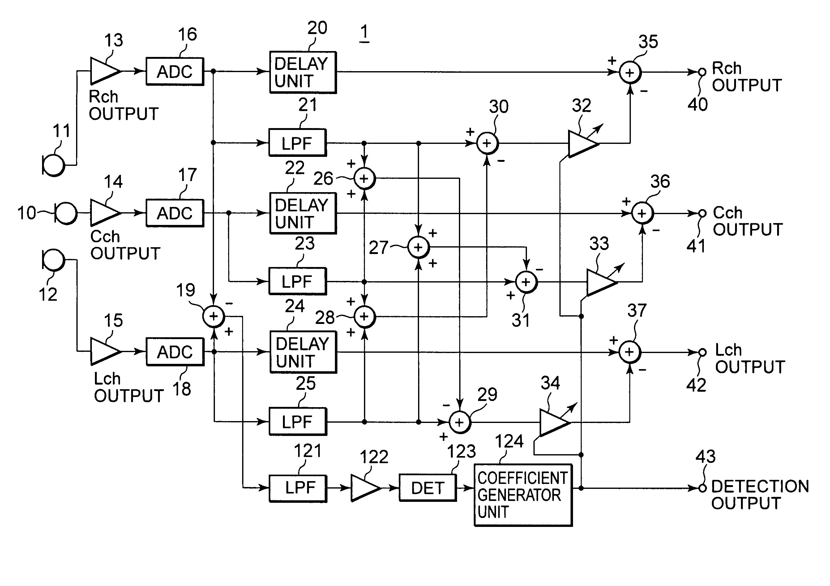
[0048]By referring to the accompanying drawings, an automatic wind noise reducing circuit and an automatic wind noise reducing method according to a present invention is described. First, in order to make the overall description easier, a frequency characteristic of a wind noise signal in a typical video camera (VTR of a type integrated with a camera), and an example of a conventional L / R two-channel wind noise reducing circuit are described.

[0049]Frequency Characteristics of Wind Noise Signals

[0050]FIG. 4 is a diagram showing an example of frequency characteristics of wind noise signals to be collected typically by a video camera. As shown in FIG. 4, a level of the wind noise signal increases following 1 / F characteristics (where F is a frequency) from approximately 1 kHz toward the lower frequencies.

[0051]However, because the level thereof decreases in an extremely low frequency depending on the characteristics of microphone units to be used or due to the influence of a coupling ca...


PUM


Abstract

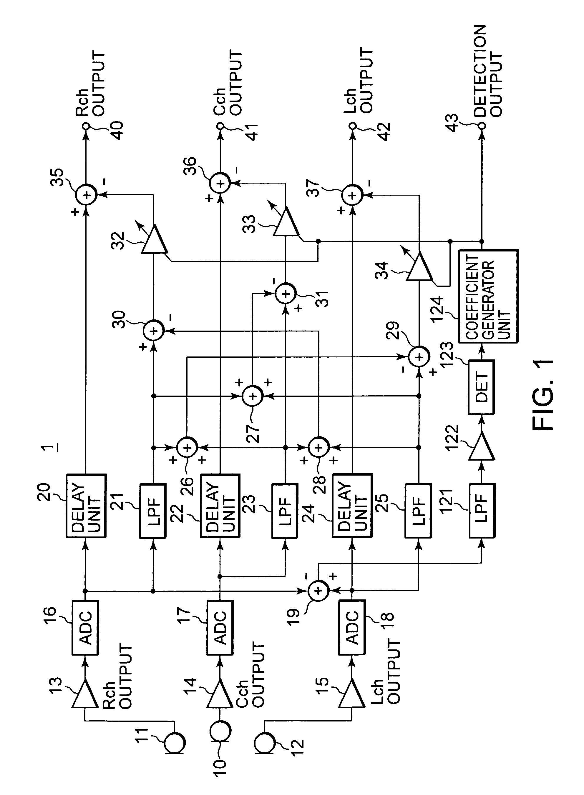
An object is to provide an automatic wind noise reducing circuit and an automatic wind noise reducing method, which are capable of coping with a multichanneling trend of audio signals, and improving performance as well as the degree of freedom in system design. Arithmetic units (26, 27, 28) obtain added signals of audio signals of audio channels excluding respective selected audio channels, which are selected so as to be different from each other. Arithmetic units (29, 30, 31) subtract respective added signals of the arithmetic units (26, 27, 28) from corresponding audio signals of the selected audio channels. The subtraction signals from the arithmetic units (29, 30, 31) are subjected to a band limit control and limited to a frequency band of a wind noise signal by LPFs (21, 23, 25). After level-controlling of the subtraction signals from the arithmetic units (29, 30, 31) which are limited to the wind noise signal band by variable level amplifiers (32, 33, 34), the subtraction signals are subtracted from respective audio signals of corresponding audio channels.

Description

TECHNICAL FIELD[0001]The present invention relates to an automatic wind noise reducing circuit for reducing a wind noise of an audio signal to be processed in an audio signal processing apparatus such as a digital video camera or the like and a method thereof.BACKGROUND ART[0002]In a VTR of a type integrated with a camera such as a digital video camera or the like, it is typically practiced that audio sounds are gathered using a plurality of built-in microphones which are disposed at an arbitrary distance therebetween, and they are recorded as a stereophonic sound signal of two channels of L (left channel) and R (right channel) in a recording medium via a directivity calculation circuit.[0003]Further, in an outdoor image shooting using the VTR of a type integrated with a camera, in most cases of conventional imaging, a wind noise due to a wind sound is inevitably collected together with an audio signal, which makes it very disturbing and irritating to listen thereto. However, a syst...

Claims


Application Information

Patent Timeline
Patent Type & Authority Patents(United States)
IPC IPC(8): H04B15/00H04R3/04G10L21/0208G10L21/0232H04R3/00H04S5/02
CPCH04R3/005H04R2410/07H04R2499/11G10L21/02
Inventor OZAWA, KAZUHIKO
Owner SONY CORP
Learn More